- VCF South West - June 14 - 16, Davidson-Gundy Alumni Center at University of Texas at Dallas
- VCF West - Aug 2 - 3, Computer History Museum, Mountain View, CA
- VCF Midwest - Sept 7 - 8 2024, Schaumburg, IL
- VCF SoCal - Mid February 2025, Location TBD, Southern CA
- VCF East - April 2025, Infoage Museum, Wall NJ
-
Please review our updated Terms and Rules here
You are using an out of date browser. It may not display this or other websites correctly.
You should upgrade or use an alternative browser.
You should upgrade or use an alternative browser.
CBM PET 3032 STRANGE BOOT
- Thread starter Desperado
- Start date
daver2
10k Member
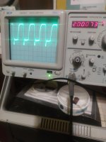
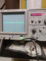
All the pins apart from pins 3 and 12 checkout OK.
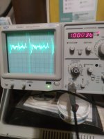
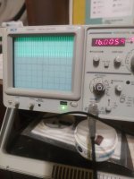
Pin 12 is not used on the PET, but it should not look like the oscilloscope waveform does.
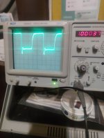
The interesting thing is that measuring the 16 MHz clock input pin is fine, as are the other clock outputs from it (pins 2, 6 and 7).
There is either something wrong with the device in G5, or G5 pin 3 is inadvertently wired to something else (or there is some conductive contamination somewhere).
Putting your probe on G5 pin 3 should NOT cause the squeal that you are observing. The frequency should be 8 MHz, but the oscilloscope is measuring 5 MHz.
You haven't also provided other information I asked for, so let's get that now shall we.
1. Was E11 installed or not when you were performing these measurements?
2. Was the original device is G5 a 191 or an LS191 or what?
3. What have you got in G5 now?
Once I get answers to these questions, I will tell you what to do next.
Dave
Pin 12 is not used on the PET, but it should not look like the oscilloscope waveform does.
The interesting thing is that measuring the 16 MHz clock input pin is fine, as are the other clock outputs from it (pins 2, 6 and 7).
There is either something wrong with the device in G5, or G5 pin 3 is inadvertently wired to something else (or there is some conductive contamination somewhere).
Putting your probe on G5 pin 3 should NOT cause the squeal that you are observing. The frequency should be 8 MHz, but the oscilloscope is measuring 5 MHz.
You haven't also provided other information I asked for, so let's get that now shall we.
1. Was E11 installed or not when you were performing these measurements?
2. Was the original device is G5 a 191 or an LS191 or what?
3. What have you got in G5 now?
Once I get answers to these questions, I will tell you what to do next.
Dave
Desperado
Veteran Member
- Joined
- Nov 25, 2017
- Messages
- 6,827
No, im waiting for a new spare!1. Was E11 installed or not when you were performing these measurements?
74191 original...also new spare part is a 74191 but i think that's bad ic...i ordered new one from another seller...2. Was the original device is G5 a 191 or an LS191 or what?
daver2
10k Member
So I assume you have the device that failed the logic tester in the PET?
Dave
Dave
Desperado
Veteran Member
- Joined
- Nov 25, 2017
- Messages
- 6,827
Yes Dave...so im waiting for the other 191So I assume you have the device that failed the logic tester in the PET?
Dave

daver2
10k Member
Ok,
So G5 pin 3 should ONLY be connected to E11 pin 2.
Remove devices G5 and E11 (if not already removed) and, with the power off and using your multimeter to check for resistance, make sure that G5/3 is connected to E11/2 (and is a low resistance - use a low resistance range).
Then, with a bright light and magnifying glass, check the PCB track out visually all the way from G5/3 to E11/2 looking for track breaks or damage (unlikely) or a buildup of flux or contaminants (more likely). You should know what to look for by now (green, white or black 'stuff' that shouldn't be there).
Use your multimeter on a high resistance range to check to see if G5/3 is connected anywhere where it shouldn't be by putting one probe on G5/3 and using the other probe on any nearby IC pins, component leads or other PCB tracks in the vicinity of the track we are chasing from G5/3 to E11/2.
Take your time and be methodical. Remember the corrosion under the ROM socket?!
Dave
Desperado
Veteran Member
- Joined
- Nov 25, 2017
- Messages
- 6,827
I am desperate 'cause there is a perfect continuity between G5/3 and E11/2....Ok,
So G5 pin 3 should ONLY be connected to E11 pin 2.
Remove devices G5 and E11 (if not already removed) and, with the power off and using your multimeter to check for resistance, make sure that G5/3 is connected to E11/2 (and is a low resistance - use a low resistance range).
Then, with a bright light and magnifying glass, check the PCB track out visually all the way from G5/3 to E11/2 looking for track breaks or damage (unlikely) or a buildup of flux or contaminants (more likely). You should know what to look for by now (green, white or black 'stuff' that shouldn't be there).
Use your multimeter on a high resistance range to check to see if G5/3 is connected anywhere where it shouldn't be by putting one probe on G5/3 and using the other probe on any nearby IC pins, component leads or other PCB tracks in the vicinity of the track we are chasing from G5/3 to E11/2.
Take your time and be methodical. Remember the corrosion under the ROM socket?!
Dave
If i put multimeter probe on G5/3 i have continuity ONLY with E11/2....not with other vicinity...
daver2
10k Member
Sorry, but you haven't spent enough time checking out the second part of the quest...
Have you followed the PCB track from G5/3 to E11/2 checking EVERYTHING near to where it goes? Especially if the PCB track is routed underneath an IC socket?
Dave
Have you followed the PCB track from G5/3 to E11/2 checking EVERYTHING near to where it goes? Especially if the PCB track is routed underneath an IC socket?
Dave
Desperado
Veteran Member
- Joined
- Nov 25, 2017
- Messages
- 6,827
no...these test for tomorrow Dave! Thanks so much and good nightHave you followed the PCB track from G5/3 to E11/2 checking EVERYTHING near to where it goes? Especially if the PCB track is routed underneath an IC socket?