• Please review our updated Terms and Rules here

CBM PET 3032 STRANGE BOOT

That makes sense also now...

Do you now see how important following instructions are?

Putting your probe (configured as X1) onto G5 pin 3 loads it up too much to the point that it seemingly malfunctions. Switching the probe to X10 overcomes this issue.

DON'T FORGET TO NOW CHANGE YOUR PROBE BACK TO X1 AND SET THE Y KNOB ON YOUR OSCILLOSCOPE TO 1 V/DIV.

Right power off and plug in your replacement LS165 into E11...

Then we can hold a memorial service for G5...

Dave
 
I have the two video ram, nivag's board with cpu and the roms ( with pettester rom )...
 
So run the PET with Nivag's board emulating the RAM and PETTESTER - so we are only really testing the video sub-system of the PET and see how it runs when it warms up.

I would also see if the display is still susceptible to your 'damp finger' test...

Dave
 
Daver2:

It might pay for Desperado to leave his scope probes on x10 permanently and his scope Attenuator on 0.1 or 0.2V/division, just in case he runs into more loading issues with the probe on x1. I nearly always use my switchable scope probes in x10 mode or just use x10 probes. It can also help protect the the scope's input Fets too, with accidental contact with high voltages. (often for VDU's I use a x100 probe to help avoid any over-voltage accidents).

Desperado:

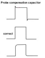
If you look at the probe plug, where it plugs onto the scope, there is normally a small hole there to gain access to a small variable capacitor. When you buy a probe for a scope, or use it for the first time, you are supposed to adjust that variable capacitor when the probe is in x10 mode. The probe tip is connected to the test point on the scope's front panel, on the lower left of your scope. Normally, there is a fast rise & fall 1kHz square wave there, or similar. The idea is you adjust that small capacitor in the probe for the most rectangular looking waveform. this is called "compensating the probe". You have a lot of overshoot in your recordings, so I think your probe is not compensated correctly. See attached.
 

Attachments

  • pcomp.jpg
    pcomp.jpg
    13.4 KB · Views: 2
Daver2:

It might pay for Desperado to leave his scope probes on x10 permanently and his scope Attenuator on 0.1 or 0.2V/division, just in case he runs into more loading issues with the probe on x1. I nearly always use my switchable scope probes in x10 mode or just use x10 probes. It can also help protect the the scope's input Fets too, with accidental contact with high voltages. (often for VDU's I use a x100 probe to help avoid any over-voltage accidents).

Desperado:

If you look at the probe plug, where it plugs onto the scope, there is normally a small hole there to gain access to a small variable capacitor. When you buy a probe for a scope, or use it for the first time, you are supposed to adjust that variable capacitor when the probe is in x10 mode. The probe tip is connected to the test point on the scope's front panel, on the lower left of your scope. Normally, there is a fast rise & fall 1kHz square wave there, or similar. The idea is you adjust that small capacitor in the probe for the most rectangular looking waveform. this is called "compensating the probe". You have a lot of overshoot in your recordings, so I think your probe is not compensated correctly. See attached.
Yes Hugo I've already set it up before...
 
White flag now... after 8 dram passes the video glitch come back :(
If i touch with finger near Char Rom, difect disappear for some seconds :(
I am desperate now!!
 
Back
Top