• Please review our updated Terms and Rules here

CDOS and TU-ART serial board drivers

Unfortunately, I have lost my electronic copy of the PRI schematic - so I will have to dig out my paper copy (which is easier said than done at the moment)...

However, you can't do what you are doing...

The STROBE signal should be generated automatically by the PRI board when you write to I/O port 54h.

However, before you do that, the printer must not be BUSY (and, therefore, the /ACK signal must be in the correct state).

You have to wait for the printer to be available (by polling port 54h and looking at the BUSY signal).

Then you can write a character to port 54h (thus generating the /STROBE), the printer sees the /STROBE signal and starts to print the character you have specified. See: https://w140.com/tekwiki/wiki/Parallel_printer_interface and https://pe2bz.philpem.me.uk/Comm01/- Digital/- Computer/P-101-ParalellPortInfo/parallel.htm and https://hw-server.com//parallel-port-lpt-ieee-1284 for more information.

I think by writing 4 to port 53h you can set the D3 interrupt enable LED to ON, and by writing 0 to port 53h you can turn it OFF agin. Do NOT write anything to port 54h when D3 is illuminated though. This could well generate an interrupt and the Cromemco will crash...

What have you actually got the PRI card wired up to, and how is it wired?

EDIT: Actually, writing anything to port 54h should cause the data bits to appear on the data line outputs from J1 of the PRI card. You should be able to check these with a multimeter or logic probe. TODO: Check where the pull-up / termination resistors are...

Dave
 
Last edited:
I might have found the problem.
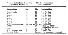
The PRI doe not have a normal pinout. Strobe should be pin 1 but it is pin 22.
All of the pins are different. I think it is working but I have to build an adapter cable.
Just like the 4FDC and TUART everything is a little different or designed before a standard so it takes a little modification to make them work
There is a more detailed PRI manual with a print date of 1982 that shows how a standard DB25 parallel printer cable pinout should be wired to the connector on the PRI board - see the figure I have attached.

I suggest you sign up for access to the Cromemco file and document repository on Github:
Give the process of getting signed up a bit of time. The contents of that repository is invaluable to someone like yourself who is restoring a Cromemco system.
 

Attachments

  • PRI printer port pinout.jpg
    PRI printer port pinout.jpg
    63.9 KB · Views: 3
Last edited:
After rewiring the cabling the printer will print goofy characters. I am thinking the next problem is that the PRI board supplies only 7bits of data.
I am using an Okidata ML390 which from what I can tell does not support 7bit data.
I am not sure if that is a thing but I have found some printers have the option to change between 7bit and 8bit.
I am looking at some Okidata ML184 printers on ebay. not too bad priced and I think they support 7bit

I will sign up to the github/cromemco repo

thank you for all of the help. Once I find a 7bit printer I will report what I find. I assume it will work
 
That is unlikely to be your problem I am afraid...

Output an 'A' to the printer and check the data lines for a hex 41 with a multimeter or logic probe (although the data lines may be inverted).

Most/all printers would/should work with 7 bit data (bog standard ASCII). If the eighth bit IS a problem, it can be tied LOW or HIGH as appropriate.

Dave
 
Thank you HMB for the pinout of the connectors and the advice.
I found that the Signal ground should not be connected to pin 14 since that is printer select. I hooked it to pin 18.
That didn't make it work but after connecting data bit 7 to ground it works! so I guess with this printer you cant leave the last bit floating.
Also: on the PRI board, LED D4 is lit up solid. I think once it get an ack signal from the printer it stays on
IMG_20240122_110121348.jpg

Thank you to everyone that has helped. this ha been a very interesting journey so far. I still have a lot to do but for the most part the TUART and PRI interfaces are working.
 
Yes, D4 is the acknowledge signal indicator from the printer.

Good work...

Have you found a readable PRI schematic?

Dave
 
Yes, D4 is the acknowledge signal indicator from the printer.

Good work...

Have you found a readable PRI schematic?

Dave
Dave - if you have a schematic for the version of the board under discussion (ie the second version of the PRI, which has fully populated board) please post it. I have not been able to find a schematic for this version anywhere.
 
I have not been able to find a schematic either. And I thought I had a copy of the newer manual but everything I am finding seems to be the 1979 version.
Once again thanks to everyone that has helped out. Getting this far would have been impossible without the information that has been posted here.
I am sure I will have more questions. I have had a lot of issues with not analyzing the way cables are wired and being in a 'PC' mentality that if it fits, it is electrically ready you just need the right software.
 
>>> I have had a lot of issues with not analyzing the way cables are wired and being in a 'PC' mentality that if it fits, it is electrically ready you just need the right software.

This 'used' to be the case with the Cromemco of course. You purchased the printer, card and cable(s) from the Cromemco dealer, configured them according to the manual, plugged them in, installed the software and the equipment worked...

Unfortunately, now we have to do a lot of computer archaeology: finding the correct revision of the manual (that is readable) for the card you bought from eBay, testing the card out to make sure it really works before use, ensuring you read and thoroughly understand how to hook up a piece of hardware and tracking down the correct software.

It is all good 'fun'!

Dave
 
Back
Top