• Please review our updated Terms and Rules here

Commodore 1901 Monitor repair

demonlg

Veteran Member
Joined
May 22, 2016
Messages
544
Location
Italy
Hello at all, again another monitor. Please help me :)

I bought this monitor for a few euros knowing that it was not working, often these monitors have nonsense to fix and I wanted to tempt fate.The monitor arrived to me a week ago, really pitiful conditions, it was obvious that it had taken excessive humidity, once opened I found parts ironed, very dirty board, so I proceeded to clean everything thoroughly and start the tests.

At the first start-up it was immediately seen that there was no HV and not even audio, measuring the power supply voltages they were completely absent or very low, I immediately thought of a short circuit and started looking for faulty components.After isolating the power supply from the rest of the components I verified that the power supply stage had problems, so I changed some capacitors and solved the first problem.

Then I followed the power supply tracks and found: BU508D on horizontal deflection shorted, 7812 voltage regulator shorted, TEA2017 malfunctioning all to the point of knocking the 24v power supply almost to 0.

I also changed the EAT transformer because it had marks on the plastic that I didn't like, once these components were replaced, the monitor finally turned on with audio also working, I connected a C64 on composite input and I saw that for a few seconds after turning on the colors were visible perfectly and then switched to black and white and after going out of horizontal frequency, the screen slowly starts to move to the left and then you see all the messed up lines of the current image, as if someone was adjusting the horizontal frequency trimmer going out of range.

I then noticed this and said that it does it about 40/50 seconds after turning it on each time, but only if I turn it off for a few minutes, if instead I turn it off and on again immediately the problem remains present.

It seems as if there was a component that by heating up shifts the horizontal frequency, I tried to cool the components on the PAL/RGB module that this model has on a separate card but nothing changed, same thing cooling the TDA3506 integrated circuit, the problem remains.

Do you have an idea or can you help me understand what it could be? I would like to point out that the way this monitor was designed it is very uncomfortable to be able to work on it while everything is mounted inside it.

I attach the schematics of bot board main and pal/rgb module.

Thanks

Emanuel
 

Attachments

  • Main schematics.pdf
    1.3 MB · Views: 2
  • pal-rgb module schematics.pdf
    1.3 MB · Views: 1
For the color i have solved, jumper on pal/rgb module SL17 closed and now i have perfect colors, the attached video is the issue, now for little video file to send i have reduced time, but normally when monitor is cold this issue is presented after 30-40 seconds.
 

Attachments

  • VID_20240903_141415.mp4
    5.7 MB
Last edited:
I would look around the TEA 2017 IC.

That looks responsible for both the horizontal and vertical oscillator and drive.

I see there is a preset potentiometer there for HORZ FREQ. What happens if you adjust this potentiometer? Make a note of where it is to start with though! It could be that the frequency lock is just on the edge or the potentiometer is intermittently faulty.

If you think it is temperature related, this might be the IC to cool down...

Dave
 
Hi Daver how are you? Thanks to reply,

the TEA2017 is new buyed in a electronic component shop, the old one result totally shorted propably caused from the 7812 problem (shorted), i have tryed to cool down it but nothing is changed, i have suspect too for potentiometer, and any little electrolytic caps in this zone, i have desoldered and tested one to one here, but not replaced all.

I have cooled down all chip in pal/rgb board and the TDA3506, but nothing. The problem seems a classically electrolityc caps issue.

It seems to be a temp problem, because if i turn on monitor when cold it's working for about one minute with very good image, if i turnd OFF and then ON rapidly when the problem is present, the problem stay present, then if i turn OFF and stay any minutes then turn ON again i have again good image and the shifting to left of the screen and then out of freq, and it seems horizontal frequency problem!

Component replaced are:
EAT
both BU508D (one shorted on EAT drive)
TEA2017 (shorted)
7812 (shorted)
TDA4601 (on power supply section for precaution)
all electrolityc caps but not aound the TEA2017

I have placed scope probe on pin 20 of pal/rgb board to check the 15,66khz but i have about 6 khz with or without problem present.
 
I am fine thank you. You?

I can't actually find pin 20 on the pal/rgb schematic. Am I going blind?

I did find the 7812 voltage regulator - so I was a little worried that it was powering the TEA 2017...

Dave
 
Fine too.

The pin 20 is on the pal/rbp connector board in upper left of schematics ( if rotated of 90° to right from attached file).

Yes 7812 power the TEA.....probably the old one have damaged the old TEA. I have replaced it with same component 7812CV (old one are 7812CT), but now i don't have checked if the 12 volt rail is stable or not.

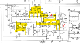
Then i have studied part of this circuit attached, i thinks so this is the circuit for sync signals, i have marked two coils of deflection with H and V.

I'll try to move HORZ FREQ PL02 trimmer to check if i have any change

1725375104885.png
 
I think you may have the H and V around the wrong way.

The HLIN inductor should be in series with the H deflection coil.

The voltage feeding in to the 7812 is only 16V. So, even if it went short circuit, the voltage would only have risen to +16V. This would have taken out the IC of course. It might be worth looking at the capacitor voltage ratings around this area in case any are (say) < 25V.

Dave
 
The is a sudden change in the operating frequency of the H oscillator. These oscillators have a base frequency that is set by non-electrolytic capacitor (they are usually mylar or similar) , resistors and they are DC voltage controlled , they are in an AFC (automatic frequency control) feedback loop, very much like the design of a PLL circuit. The frequency of the incoming sync is compared to the H oscillator frequency and an error voltage is created to bring the DC controlled oscillator into lock with the incoming sync.

Therefore, if there is anything wrong in the AFC loop, DC voltage control, or the base running frequency of the oscillator, the first thing is that the picture phase shifts, meaning the picture moves left or right, just as it does when you turn the H hold control, then if it shifts too far the AFC loop goes out of lock, and the picture falls on its side into multiple tilted bars.

So it appears something in the H osc and AFC system has gone intermittent and or tempertaure dependent. You could try cooling individual components around the IC with freeze spray of with some contact cleaner on a cue tip to give more precise areas of focal cooling to various components. You also need to check the stability of the DC power supply feeding that area, any changes in that could cause the effect.

Look up the data sheet/application notes on the TEA2017, and it will explain which parts of the IC and its pins perform the H osc and AFC functions.
 
Last edited:
I have downloaded datasheet but i don't have found AFC and H oscillation notice, or i don't see...
 

Attachments

  • TEA2017.PDF
    411 KB · Views: 4
Pins 3, 4 and 5.

Pin 3 is the flyback input. This feeds one input of the phase detector. The other input of the phase detector is derived from the sync separator that is fed from the composite video input pin pin 7.

It looks like a the input signal (separate H and V and video) is combined into a composite signal and fed into the H and V oscillator module (TEA2017). If this is true (and I am not imagining it) then it may not be the TEA2017 that is faulty, but the circuit producing the composite signal for the TEA2017. Monitor pin 7 and see what it looks like when both cold and hot.

Pins 4 and 5 seem to be related to the timing?

Pin 5 appears to be connected to the HORZ FREQ potentiometer.

Dave
 
Last edited:
Yes, pin 5 of TEA is connected to the PL02 HORZ FREQ potentiometer.

For testing i have to make a board out of the monitor BOX, when mounted is not possible to check anything!
 
Solder some temporary wires onto the point(s) you wish to monitor and bring them out to a 'chocolate block' connector. You can then install the PCB and take your measurements from the outside...

Dave
 
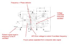
I have attached a modified diagram to show the important parts of the H AFC system.

Of note three things, the VCC1 and the value of the resistor and the capacitor on pin 5 determine the center running frequency of the H osc. The DC control voltage out of the phase detector can bend the frequency up and down to pull the H osc into lock.

As noted it is an automatic frequency control (or automatic phase control) system that locks the H oscillator to the incoming H sync pulse frequency. Once locked any forced changes inside the loop, such as moving the H hold control causes the locked phase relation to change a little and the picture will shift left or right untill pushed too far and falls out of lock.

Make sure that the voltage regulator output that supplies the VCC1 is stable, and has adequate heat sinking if it needs it.
 

Attachments

  • Hosc.jpg
    Hosc.jpg
    196.4 KB · Views: 6
Last edited:
Input of regulator are 16.2 volt and output is very stable 12.4 volt measured on 12v sign on schematics now i have to check on pin 4 of TEA?
 
With scope, also i have desoldered CL08 and its value is correct 22nf
 
Last edited:
CL07 is new CL09 i have to desolder this, it is a 10nf but i don't know a voltage range, probably is 50/100 volt max, tomorrow i desolder it and try to solder wires on pins 4 and test point 7 (pin 5) of TEA
 
Back
Top