• Please review our updated Terms and Rules here

Commodore 1901 Monitor repair

One problem with this sort of fault is that whatever change is occurring inside the loop, the loop will move in a direction to compenstate for that change. So lets say there is a problem in the phase detector, either due to a defect in it, or the siganls feeding it (separated sync or the H flyback pulse) the DC Control voltage will skew the H oscillator, then that will case some cancellation of the problem in the phase detector.

Or likewise if the defect is an unstable base frequency in the H oscillator section, the DC output of the phase detector will move to negate some of the change.

In other words a fault anywhere will produce a change everywhere in the H. AFC control system because of the feedback loop.

To get to the bottom of where the fault resides, it is required to break feedback the loop. This is done by disconnecting RL10, where it connects to pin 4, and then feed RL10 with a DC Voltage from a variable power supply so that the H oscillator runs at close to the correct frequency. When that is the case the picture will bee seen to float by horizontally. It is then easy to see if the H oscillator is basically stable, or not and if there are any sudden changes in frequency.

In addition, the voltage output from the phase detector can be monitored with the meter or scope. If the fault is there, there will be a sudden DC shift in its output. This could be due to something happening to the H sync pulses in the composite signal or the separated H sync pulses or the flyback signal. (If the H osc was stable with fixed DC control the flyback frequency would be stable, but its amplitude might not be by the point it gets back to the IC)
 
Hi Hugo

So a problem with the new TEA2017 that I installed is not to be ruled out? This makes it difficult for me to do further checks, unfortunately I am not 100% equipped for these things, but I would be very sorry to put this monitor aside.
I was thinking of checking CL09 and the resistors in play in that area you indicated, or I was thinking of turning on the monitor trying to keep the card outside the case and try to cool the components in that area, but only because I assumed a change due to temperature, but at this point I have doubts.
 
I have bought TEA in a online shop of a notoried electronic shop in ROME, chip arrived and pins are not used and new, but is an old stock, i have another one ordered from other seller in France.

But, previously, the faulty TEA did not start the high voltage at all and the RP16 resistor smoked on power supply and the 24v dropped to 6v, I understood it was the TEA by thinking about what powered it, in fact after removing the TEA the RP16 resistor remained intact, and the voltage remained stable.

Today I also wanted to try moving PL02 to see if anything changes, I have to check if I can reach it with the plastic screwdriver from outside the case.
 
Last edited:
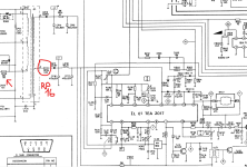
I can't see RP16 on the schematic.

If it 'smoked' you did replace it didn't you?

Dave
 
Last edited:
Yes is an error on schematics, is this one with circle, is marked with RP06 but on the board is marked RP16, the RP06 is the other one with red arrow, and yes replaced with a resistor fuse same value:


1725440606819.png
 
Looking at the internal diagram for the TEA2017, the parts of it that relate to the H phase detector, H oscillator etc, are low power signal circuits. The power stages in it are for the vertical scan circuitry that drive the yoke's vertical coils directly. It was probably the vertical output stage section of the original IC that had failed & was drawing excessive power supply current via its pin 12. It would be unlikely the replacement chip was defective in the Horizontal sections, but it is not impossible. It would be worth trying another to be sure.
 
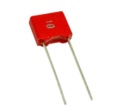
I have found in my component store a 10nF 63v Wimar capacitor, it's ok to try replacing CL09 ? Is this:

1725444153974.png
 
If you intrested i have checked the old TEA removed, it is in short from pin 8 (GND) and pin 15 (directly connected to deflection coil BA02) and now the question, the BA02 is horizontal or vertical coil? (From schematics i think so it is horizontal coil)

Is possible a broken component around pins 12,13,14,and 15 of TEA?
Just as Daver2 said, BA02 is the Vertical scan coils.

You can see from the circuit the BA03 coils ( H scan coils) are in the collector circuit of the BU508, which is the H output transistor TL02.This is driven by a driver transistor TL01 (the BC639) and the H oscillator in the TEA2017, via CL19 drives the BC637.

The TEA2017, has a power stage that drives the V coils directly from its pin 16. All of that vertical scan system is (should be) independent from the Horizontal scan system. The only interaction is that a parabolic shaped vertical voltage, derived from some of the integrated vertical scan current (developed across CF06 and integrated by it) is used to modulate the amplitude of the H scan a little (this is the East-West modulator, of note if you integrate a sawtooth wave you get a parabola, it is an interesting mathematical relation that is not particularly intuitive) via the transformer LE01, this is to gain straight sides on the raster scan (correct its geometery). In other words as the V scan progresses from top to botton, the amplitude of the H scan is manipulated a little to keep the sides of the raster straight.

One "big trap" notice that there is a component conspicuously absent from the schematic, it is the energy recovery diode (or damper diode). It is actually in the BU508D transistor connected from its collector to its emitter, it is critical in scanning the left side of the raster, yet the person who drafted the schematic didn't draw it inside the transistor (go figure). This is often why specific parts replacements are important. A transistor without the diode in it would self destruct in short order. THe data sheets sometimes call this diode a "freewheeling diode" not a great name. In TV applications, energy recovery or damper diode or efficiency diode is a better name. It returns stored magnetic energy in the yoke and flyback transformer, in a controlled & heavily damped manner, to the power supply immediately after flyback, to scan the left side of the raster.
 
Last edited:
Yes BU508D is different to BU508A or AF, the D indicate a dumper diode integrated in a transistor.

I have a similar issue you indicated in a 1084 commodore power supply, originally the power supple use 2sc1575 in a switching circuit but i have replaced it with BU508AF, monitor working perfectly for 3-4 time power on then the BU going to shorted again, i try to use the BU508D.

Now, i have a static moment for my 1901......i don't know where initiate to check, i have found only new CL09 caps to replace.....
 
I would check pin 7 of the TEA2017 first.

This should remain constant before and after the problem.

Dave
 
I have resolved, replaced AN5620X on the RGB/PAL board and CN09 faulty when hot.

Now is perfectly working.

Tomorrow i check all regulations for gain focus on fbt and colors.

Thanks for the support, now in the next day i recall other old post for the strange problem on 1084SD2.

Good night at all
 
Back
Top