• Please review our updated Terms and Rules here

Commodore B128 (C610)

So I wanted to post an update on my issues.

As I left it, the computer was working, but intermittently, and would frequently work okay in BASIC for a few minutes, but then lock up and drop into the machine-language monitor. For instance, I wrote a short BASIC program to print numbers to the screen in an infinite loop - it would run for a few minutes and then lock up with no-one touching the computer the whole time.

I was planning to replace the power supply, since the filter capacitor failed on that, and it may have been the source of the issues. I did some other basic testing as a final ditch try before replacing the PS. I didn't feel fully sold that the power supply was the source of the problem, as my basic checking of it did not reveal anything amiss.

I removed the motherboard shielding cardboard, and found it was maybe a little more reliable without this, but it still was not working consistently.

I then noticed that I could induce it to lock up by pressing on one of the chips (U1 specifically). Looking back, I had also noticed that several times that it locked up when I moved the computer slightly while it was running, and once when I pressed down on the top of the enclosure lightly. I had dismissed this as just randomness, but they came back to my mind after inducing the lock-up.

All these things made me think I had a loose connection somewhere, likely with one of the socketed chips.

So reviewed the motherboard schematic, and I mapped out all the pins of U1 (6526) and U9 (6509), and I checked each of them for continuity, and also when pressing down on the chips. All of it checked out fine.

So then, I pulled U1, U9, the small 3-EPROM daughterboard, and its 3 EPROMs, and cleaned all the pins with alcohol, and coated them in a light coating of Caig's DeOxit. I also used a spare pin pulled from a female header, which closely matched an IC pin for thickness, and dipped it in DeOxit, and pressed it into each socket position several times, re-wetting it every 2 pins.

So all this done, I replaced all the chips and fired up the computer again.

The BASIC message came up fine - so far so good. I ran a short BASIC program looping and printing, and it ran for over 15 minutes without issue. Looking better! I then pressed down on the computer case, slapped it, lifted corners, pressed down on chips, and it continued to run without issue. Now I was getting very encouraged.

I connected my PetSD+ and loaded up several programs, typed a document on the word processor, and saved it. Exited and loaded up again, and it worked great. In all, I spent about 30-40 minutes on it without any issues.

This is looking very encouraging! I will continue to test it and report what happens.

If I'm reasonably sure I've fixed the problem, I'll go ahead with replacing the power supply, as I have it sitting right here. I didn't want to introduce another variable to the computer if it could be helped, but now it looks like the issue has been resolved. I don't like running this computer off the cheap 220V transformer, as I can't be sure how clean the power is coming out of it, and it's just a pain.

So this is my first experience with Caig's DeOxit, and I must say I'm impressed with it!

Congratuilations first of all for fixing such an intermittent problem, they're the most painful ones!
However, regarding the transformer: if it's just a transformer, the one with iron E-I core (or toroidal) and windings, well, it can't introduce any more noise in the output voltage than what is present on the input side (somehow, it's the contrary as it has finite bandwidth), that's of course assuming you're using it below it's rated VA power.
One of the easiest way to convert a 220V input SMPS to 110V input is to change the input circuit topology from a diode bridge + capacitor to a two diode + two capacitors doubler. It usually involves installing one jumper if the input capacitor is already a series of two identical capacitors, or splitting the single capacitor in a series of two (of half the original rated voltage, so, 200V DC in this case, and twice the original capacitance), then again bypass half the bridge to the middle of the capacitor series to obtain a voltage doubler rectifier.
Of course all this can be attempted only by someone that feels enough at home on these high voltage circuits :)
Converting a 110V input SMPS to 220V in the case it's without a voltage doubling input is instead not worth attempting most of the times.

Frank
 
Thanks!

I tested it again, and this time ran for over an hour, and doing lots of stuff, running programs, playing music through the internal speaker, etc. It ran like a champ! I even ended it with a series of bumps and knocks, and it still ran perfectly!


I don't feel secure enough to make the changes in the power supply you've suggested. I don't have the foundation of knowledge to troubleshoot such a change in the power supply electronics, and chances are high I would miss something that would be obvious to someone who understood what they were doing, and then, KABOOM.

I'll just be happy switching out the power supply for something smaller and very likely more efficient.

Thanks for the suggestion, though!

If you do try to replace the power supply, remember, the CBM-II power supplies also generate either a 50 or 60 Hz signal for timing. Some people have made a small little addon circuit to supply this to the motherboard.
 
Yep. I bought a cheap knock-off Digispark from ebay for a few dollars. It has an ATTINY85 microcontroller on a small circuit board with 6 GPIO pins, and is programmable with the Arduino IDE. There's a function called TONE, which generates a square-wave for sound, so it can be set to 50 or 60 Hz. I did run an isolated test of this and scoped the signal, and it looked good to me. I haven't tested it on the actual B128 yet, but that's my next step.
 
Thanks!

I tested it again, and this time ran for over an hour, and doing lots of stuff, running programs, playing music through the internal speaker, etc. It ran like a champ! I even ended it with a series of bumps and knocks, and it still ran perfectly!


I don't feel secure enough to make the changes in the power supply you've suggested. I don't have the foundation of knowledge to troubleshoot such a change in the power supply electronics, and chances are high I would miss something that would be obvious to someone who understood what they were doing, and then, KABOOM.

I'll just be happy switching out the power supply for something smaller and very likely more efficient.

Thanks for the suggestion, though!

If the input capacitor is already a series of two capacitors, you just need to add a single wire jumper. The configuration you should end with it's called "full wave voltage doubler/multiplier", you can see it here:

https://www.electronics-tutorials.ws/blog/voltage-multiplier-circuit.html

But anyway, I know one must feel comfortable to modify line voltage equipment :)
Frank
 
Congratulations on fixing the machine.

Just wanted to add that your plan to use a Microcontroller to produce 50hz is a bit too complicated I think (sorry don't get me wrong). You can reproduce the 50Hz reasonably well with a small circuit using a 555 timer chip and some passives. I did this when I had to replace the power supply on my 710, the big brother of the 610.

Congrats again on fixing this little gem!
André

Sent from the mobile client - Forum Talker

Thanks!

Yes, I guess using a microcontroller is a bit of overkill for simply generating a 50Hz signal. From a builder perspective, it's very easy and economical, as the board is inexpensive, and it's all on a small 1" x 1" PCB with mounting holes, and the code is extremely simple. Definitely, building a circuit from a 555 timer is much more "correct" for a vintage computer such as this.

One other benefit from using the Digispark is that I have been also thinking of adding a small fan, and making it temperature controlled. If I go that route, then the microcontroller would be useful to have, as it can read the temperature and control the fan as well.

Could you post a schematic of the circuit you designed for your 555 timer, or describe what components you used and the values of resistors/capacitors for your circuit? I looked at how to design one online, and it looked complicated to me, and I wasn't sure about the mathematics of choosing components, as I've never built such a circuit.
 
If the input capacitor is already a series of two capacitors, you just need to add a single wire jumper. The configuration you should end with it's called "full wave voltage doubler/multiplier", you can see it here:

https://www.electronics-tutorials.ws/blog/voltage-multiplier-circuit.html

But anyway, I know one must feel comfortable to modify line voltage equipment :)
Frank

Hey Frank,

I thought about your "single wire jumper" solution, and I looked out on Zimmer.com, and found schematics for the power supply here:

http://www.zimmers.net/anonftp/pub/cbm/schematics/computers/b/4256004-01-left.gif
http://www.zimmers.net/anonftp/pub/cbm/schematics/computers/b/4256004-01-right.gif

On the left page, I saw there's a component labelled "E1", and it has "115VAC" written above it. I wonder if they designed this power supply to be switched easily between 220V and 110V via this jumper.

I did a similar thing on my BBC Micro Model B. In that power supply, there's a well documented modification which involves a simple wire you can solder in which converts it from 220V to 110V, and it worked great.

The issue with my B128 power supply is that I took it apart, and could not see anything resembling the "E1" indicated on the PCB. Also, I suspect my power supply does not match the above schematic, as I spot checked some other components and they did not match up.

If that schematic is correct, indeed installing E1 turns the input to a voltage doubler series configuration, so it will work on 115V.
The key for easy modification is the series input capacitors. You can see them very well, they're the biggest electrolytics on the whole circuit, 200V voltage rating. If yours have a single 385-400V big electrolytic, the mod isn't "that" easy.

Frank
 
Frank: My PCB has a bunch of large capacitors, but I'm not sure I want to try to map out the circuit to make this change on a 35+ year old power supply with these aging capacitors. I was so hopeful that the "E1" jumper would be sitting right there, and I could comfortably make the change easily.


On another note, I found a cool 555 timer circuit calculator online here:

http://houseofjeff.com/555-timer-os...om/555-timer-oscillator-frequency-calculator/

It provides lots of options for arrangements based on the desired frequency, and I think I've got all the components laying around, so I might give it a try!
 
Also, does anyone have any idea how stable the 50/60Hz signal has to be?

What does this signal do? It seems suspiciously correlated with NTSC vs PAL frequencies.

I am wondering if the frequency I generate is a bit off, will it mess anything up? What should I test to make sure the replacement signal I generate is good enough? Would I need to be able to "fine tune" it on my replacement circuit?

If it's a bit off, would be video be scrambled? Video timings are pretty touchy, from what I understand about them, which isn't much.
 
So I was encouraged by the website calculator for 555-timer circuits, and found I had the components, so I built up a prototype.

I used the following components:

C1=0.1 µF
R1=1 KΩ
R2=120 KΩ

which mathematically generates a frequency of 59.8755 Hz. with a 50.2 % duty cycle.

This seemed perfect, so I built it up and hooked it to my scope. The actual frequency was around 67Hz, which I didn't think was good enough. I then went to another 555-timer calculator website, one where you enter in your C1/R1/R2, and it calculates the resulting frequency and duty cycle. I measured the actual resistance on my resistors, and found they were a bit off (not surprising). I then plugged these actual numbers into the website, and found that if I lowered the C1 value to 0.09 uF, the resulting frequency was about 67Hz. I figured the capacitor I used was just a bit off, so I went back to the prototype, and switched that cap out. I soon found a different 0.1uF cap which yielded a nice clean 60.2Hz, with some minor fluctuations.

I felt good enough about this, so built the circuit up on some perf board and tested it. It put out just over 59 Hz, using the exact components from the prototype. I imagine the difference is due to slight differences in capacitance from the connectors under the breadboard.

I wired up my harness for the power supply replacement (a Mean Well PT-65B), and connected it up to my B128 motherboard, connected the output from the 555-timer circuit, and turned it on. It worked perfectly.

Everything ran beautifully!

Thanks Andre for the idea of using a 555-timer, and I'm happy there's not much "modern" equipment inside it like the microcontroller I was planning to use. The computer is a bit lighter as well, now that I don't have the huge transformer in there anymore, and it runs off 110V!

One more thing. I was planning on using a bleeder resistor for the +12V line, because the datasheet for the Mean Well PT-65B shows the +12V line outputs a minimum of 0.2A. I was planning to use a 56ohm/5 watt resistor, and I had one standing by. I checked the +12V line with no load, and it was around +11.7, which seemed good enough to me. I tested it on the B128 without the bleeder resistor, and it works great without it. I guess the Mean Well states it needs a minimum of 0.2A to deliver a full +12V on that line. It seems to be good enough like it is, though. I've got lots of room on my perf board for it if I need to put it in, and I've already split out the +12V line with an extension wire as I was planning to use the resistor.

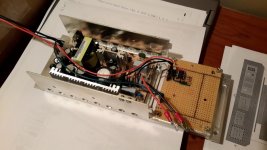
Here's a picture of my replacement power supply and the 555-timer circuit:

20181121_194222 (Large).jpg
 
Thanks!

Yes, I guess using a microcontroller is a bit of overkill for simply generating a 50Hz signal. From a builder perspective, it's very easy and economical, as the board is inexpensive, and it's all on a small 1" x 1" PCB with mounting holes, and the code is extremely simple. Definitely, building a circuit from a 555 timer is much more "correct" for a vintage computer such as this.

One other benefit from using the Digispark is that I have been also thinking of adding a small fan, and making it temperature controlled. If I go that route, then the microcontroller would be useful to have, as it can read the temperature and control the fan as well.

Could you post a schematic of the circuit you designed for your 555 timer, or describe what components you used and the values of resistors/capacitors for your circuit? I looked at how to design one online, and it looked complicated to me, and I wasn't sure about the mathematics of choosing components, as I've never built such a circuit.

Sorry for the late reply. You can find a circuit for 50Hz generation here: http://www.6502.org/users/andre/csa/pwr/csa-pwr-v1.3b-1.sch.png (from the power supply of my self-built 6502 computer)

Regards,
André

Edit: oh I see you've already found something! Sorry again for the late post.
 
Very cool. My B128 came with no power supply at all.. hoping to create one somehow. This gives me hope.
 
Very cool. My B128 came with no power supply at all.. hoping to create one somehow. This gives me hope.

OK.

Here's some important information I gathered from my research on this project.

Schematics of the B128 are here:

ftp://www.zimmers.net/pub/cbm/schematics/computers/b/index.html

Based on these, the B128 has the following power requirements: +5V @ 4.5A, +12V @ 0.2A, -12V @ 0.05A

The connector to connect the power to the motherboard is as follows:

https://www.digikey.com/product-detail/en/molex-llc/0050841065/WM2882-ND/2405430

and the pins it uses are:

https://www.digikey.com/product-detail/en/molex-llc/0002082004/WM1270-ND/133294

The 50/60Hz line can be provided using either my method documented above, or using Andre's link.

Hope this helps. Good luck!
 
Back
Top