• Please review our updated Terms and Rules here

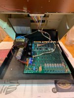
Commodore PET 2001-8 text wobbling on screen

First of all (as this is your first post) welcome to VCFED.

It was either like this when it was new. It is also possibly an 'import' and the frequency and/or voltage is different to what it was designed for.

Clearly the voltage tapping would have been changed on the transformer (otherwise the black magic smoke would have been released from the machine that makes it work) - but sometimes import modifications can have some strange effects.

You may be able to use magnetic (mu metal) shielding between the transformer and the monitor - but you are now embarking on a path that could result in lots of wasted hours.

Is it significant enough to bother you is the first question you need to ask yourself...

Dave
 
You can put a copper flux band around the transformer, if it does not already have one. Have you ever seen a copper flux band or understand how these work ?

To work, it is better of they are fairly thick copper about 0.7 to 1mm thick. The thin copper foil you may see offering to do the job is mostly fairly hopeless.

The level of magnetic radiation from the transformer very much depends on the peak core flux density (in Webers per square meter or Teslas) and it rises abruptly above a certain threshold, due to core saturation. This is proportional to the applied voltage and inversely proportional to the frequency.

Certainly in 50Hz countries, all else equal, the peak flux density is 60/50 higher for a transformer compared to running it on 60Hz supplies for the same rms supply voltage. Also if the line voltage is running higher it aggravates the problem. American 60Hz designed transformers don't do well in 50Hz countries, they tend to run hot with high range off load primary currents and have high radiated magnetic fields.

In any case one thing you can do is power the computer via a Variac, and lower the line voltage until ripple breaks through to the voltage regulator outputs (this is easy to see in the output video on the VDU), then increase it about 5 to 8 volts over that, to allow for line voltage fluctuations in your locality. This will give not only the lowest possible thermal dissipation in the analog voltage regulators in the computer, but the lowest possible peak flux density and lowest possible radiated magnetic fields from the power transformer.
 
Last edited:
Found this interesting image of a 3008 on eBay! Clearly showing a metal sheild inside the top cover directly above the transformer. Do you think this is an end user addition or dealer / manufacturer fix? Wondering if this was necessitated by the change of case material from metal to plastic for these models. Does anyone have any info on possible modifications to UK spec. 30xx machines?
s-l1600_result.jpg
 
I think that shield would help, but the transformer does not appear to have a flux band which would be the first move I would make if I had the trouble.

It is not an end user addition, two reasons, the screws that retain it fit into pre-existing threaded brass inserts in the case (I checked my machine). Plus the plate has been processed in a factory after it was cut. If it is aluminium it has been black anodized and if it is steel it has been black painted to a very uniform finish. Doesn't look like a home job (unless it was mine of course😀 )

I think , that all/most PETS like this were intended to have this shield plate, but most likely what happened was, along the way, they simply found it was not required, or perhaps redesigned the power transformer for a lower peak primary magetisation flux density and solved the problem that way, and dropped the shield. Just guessing here, but probably the earlier the generation of the PET and transformer, the more likely it might be to have required the shield.

There is another explanation too, though its a little more "Out there", not as bad as Alien abductions though:

It has been observed that many vintage power transformers appear to have high radiated magnetic flux. This has shown up in vintage radios, TV's Audio amplifiers etc. The level of hum injection from magnetic interference, in some cases has been so high that it almost seems impossible to believe that it could have been like this form new.

As noted the problem gets much worse if a transformer designed to run on 60Hz gets run on 50 Hz, even at the exact same rms line voltage and worse in either case with high range line voltages. So the question got raised....If the transformer was not like this from new, what could have changed over time to cause it to radiate higher magnetic fields ?

Keep in mind the magnetization flux is nothing to do with the load current.

One theory, and the only one that seems to wash, is changes in the magnetic properties of the core. If that was true, what would be the mechanism/s ? It could be that over time the insulation layers between the laminations fail and as a result the Eddy current losses increase and so does the primary current. To check this out, on a number of problematic transformers with the problem, I sanded down the edges of the lamination stack to make connections to the laminations, and I could not convince myself, on testing, that this had happened to any significant extent.

The other theory is, that relentless thermal cycling of the core has changed its metallurgy and magnetic properties, causing the the B-H profile of the core to start to saturate at a lower magnetic flux density than it did when it was new. This is the only theory that I think makes any sense (if it were true that the transformer was different from its new state). It is also consistent with the core saturating very abruptly on line voltages that are in the high range, and why the interference effects can drop with relatively small line voltage reductions of 5 to 10v on a Varaic. Though this theory about the core material is very very difficult to prove or disprove without a time machine.

The primary magnetization currents though are enormously different between modern and old transformers. In one case with a line transformer made in the late 1930's, of the same power rating and core size to a modern Hammond transformer with modern core materials, in the Hammond case it was 47mA, in the vintage transformer case over 500mA, at least x 10 higher. Again, the radiated fields from the old transformer were very high, so much so it deflected the beam of the CRT in a scope that it was used in significantly, and it could not have been like this from new. And zero detectable beam deflection with the modern transformer. A case like this makes it fairly convincing the transformer's original core has changed.
 
I could have mentioned that the way a shield plate like the one seen in that 3008 PET works, is the same as a copper flux band, on the principle of Lenz's law. It doesn't have to be made of special magnetic material like Mu Metal, because it works on the basis of alternating current, in that the magnetic field from the transformer induces an alternating current in the metal, and that alternating current produces an opposing magnetic field that helps to cancel the field that induced it. Of course this won't work for a constant field.

That silver reflective layer I think is not so much for magnetic shielding but it reflects away infrared heat. Reflective layers like this where often used over hot objects in tube radios & TV's to reflect heat away from plastics or composite materials. Probably has no application in a metal top PET, but, probably also the metal top PETs never needed the shield as the metal top did the deed, and the need for the shield only became evident with the plastic top PETs, explaining why these had the threaded brass inserts for the two mounting screws.

****************

What a shame those Vandals drilled holes in the pcb on that PET where the extra 4116 memory goes. They can never be forgiven for that, when they meet Saint Peter he will say, sorry you cannot come in, your were the guys who drilled the holes in those PET pcb's, you monsters.

I thought of a way to fix these. Now that very thin pcb's are readily available. One to sit over the top layer with duplicate tracks and one over the bottom layer. Its a real mess when they are repaired with wire links.
 
Last edited:
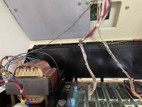
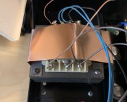
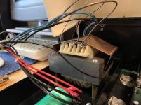
Belt and braces approach. Near enough rock solid to quell the questions of should it wobble like that and I thought you fixed it!!
The 1mm thick copper is a little tricky to deal with and solder up to create a continuous band which is a nice tight fit.

IMG_8036.jpg
 
That looks good, a flux band on the transformer and a shield plate too.

With this arrangement is there any evidence at all of magnetic interference to the CRT beam ?

( I also note it is a plastic top PET, these are certain to be the ones more vulnerable to interference from the transformer)
 
Pretty much eleminatated wobble on the CRT. Just the very slightess trace of a wobble, but I am looking very closely for it! It's a case once you have seen a wobble you almost can't unsee it.
Haven't got another PET to compare it with. Good outcome really. Definintely something that should be checked out before delving deeper to the electronics. The old adage "Eyes before Spanners"!
Yes, plastic case to PET. It can't help with interferance control.
I know exactly what you mean, once something is seen, it is hard to un-see it. But if it was in the condition it is now, you likely would have never known or noticed that there was an issue in the first place.

Good job you did there.
 
Back
Top