• Please review our updated Terms and Rules here

Commodore PET 2001 with no cursor

So, I was just reviewing the thread again to get a bit of inspiration.

If you run the ROMulator with the ROM and RAM mapped internally - this still requires the video circuitry and I/O devices (e.g. PIA and VIA) for the PET to work.

Thus is where we are having the problem I believe.

Going back to post #63, we appear to have working external RAM and video circuitry (it passes the tests).

We appear to have a faulty ROM - but that shouldn't affect us - unless the ROM is affecting the data bus in some way.

Now, the thing that has grabbed my attention is the $82 value that is displayed for each of the keyboard bytes.

This indicates that either:

1. The keyboard PIA wasn't installed, so the value is just random. However it is a non-random random value!

2. The entire keyboard matrix is returning the same byte value. This is possible with a fault in the key matrix.

3. The other interesting possibility is that this is giving us a glimps of the fault.

Dave
 
Hi Dave,

I checked the PIA keyboard connection.
all 10 connections (J5, 1-10) from the keyboard to the 74145 switch from 0V to 5V when the fitting key is pressed.
the 4 connections from 74145 to PIA are all permanently high, no response to keystrokes. Without PIA, the level on the 74145 is permanently at 1.6V.
I guess the 74145 is dead, what do you think?

Harald
 
Harald,

Please don't assume the 74LS145 is dead based upon your investigation. I will explain further after lunch.

Two 'teasers':

1. The signals flow from the PIA to the 74LS145.
2. The outputs of the 74LS145 are open collector...

You might want to download and read: https://archive.org/details/The_Pet_Revealed for a bit of homework.

There is also a lot of detail you will find at: http://www.6502.org/users/andre/petindex/.

Dave
 
Lunch over...

PA0, 1, 2 and 3 of PIA G8 drives four (4) signals into the 74LS145 G9 (BCD to decimal decoder). If the input values to the 74LS145 are in the range 0 through 9 then the appropriate 74LS145 output will be logic '0'. All of the other 74LS145 outputs not selected will be OPEN CIRCUIT (not logic '1')... This is a key fact. If the input values to the 74LS145 are 'invalid' (in the range $A through $F), all of the 74LS145 outputs will be OPEN CIRCUIT.

Note that on this particular PET there is an LED present on the board (DS1). If the signals to the 74LS145 are $B, then this LED will be illuminated - otherwise it will be extinguished. This LED is only driven by PET diagnostic software (I believe).

This explains why you are measuring 1.6 Volts on the outputs of the 74LS145 - they are effectively 'HIGH' (but this means open circuit). The voltage you are measuring arises (probably) as a result of leakage (I am guessing).

The key matrix is just that - an array of 10 by 8 keys (not all occupied of course). When a specific output from the 74LS145 becomes LOW, any closed keyswitch will potentially pull-down any voltage that is on the 'other side' of the keyswitch to the 74LS145.

PIA G8 (PB0..7) are the signals from the keyswitch matrix. Note that each input line is pulled-up to +5V via 8 off 10k resistors. Therefore, the inputs to the PIA will always be HIGH - unless a keyswitch is pressed and the line on which the keyswitch is present has been selected via the 74LS145 (i.e. the line is LOW).

The way the PET BASIC ROMs drive the keyboard is to initialise the PIA to generate an interrupt when the video blanking signal (PIA G8 CB1) becomes active. The interrupt causes the ROM to move on by one step and scan the next row of keys. If the PIA fails to be initialised correctly, the interrupt will not be generated and the four signals driving the 74LS145 will not cycle around. Basically, the keyboard scanning will only occur when an interrupt occurs. No interrupt, no keyboard scanning...

My PETTESTER works by polling the keyboard - not by interrupts. Hence getting my PETTESTER to run is key to finding out what is going wrong.

On the assumption that the inputs to PIA G8 (on port B) are all HIGH ($FF) my PETTESTER will invert and display a value of $00 for each row of keys. A consistent value of $82 displayed ($7D at the pins of the PIA on port B) would indicate that either:

1. The PIA hasn't been initialised correctly. By default, on a RESET, the PIA ports are configured as inputs.
2. The PIA is dead. Well, you have tried plenty of PIAs haven't you...
3. The address decoding is not working correctly (the PIA is not being addressed correctly).
4. The data bus is somehow getting corrupted.

These are what we need to work on identifying.

Dave
 
I am thinking that the next move is to checkout the address buffers on the PET by using the "NOP generator" built into Bitfixer's ROMulator. Set the switches to 12 (according to the documentation at: https://github.com/bitfixer/bf-romulator).

In this mode - the CPU is forced to execute a NOP instruction. A memory read is performed, but the returned data is ignored and replaced by a 6502 NOP instruction ($EA).

If you measure the signal on BA0 (E2/11) it should be a squarewave of 250 kHz.

If you measure the signal on BA1 (E3/4) it should be a squarewave of 125 kHz.

Carry on for each BAn signal (http://www.zimmers.net/anonftp/pub/cbm/schematics/computers/pet/2001/320130-1.gif). Each higher address line should measure half the frequency.

There is not a BA12 through BA15 - measure these instead on pins 23, 22, 21 and 20 of G2 (74154).

See how that goes. There will be some further measurements to take once after you have done this.

Dave
 
Hi Dave,

E2 and E3 are hidden under the ROMulator, I can’t reach to the pins. Got the signals at J4, pin1,2,3… with 250kHz, 125kHz…
BA9 = 500Hz, BA10=250Hz, BA11=125Hz, BA12=60Hz, BA13=30Hz, BA14=15Hz, BA15=7,5Hz

Harald
 
Meeting finished...

Observe G2 (74154). This decodes the upper 4 address lines into 1 of 16 outputs. Ignoring pin 1 of G2 for now (/ZERO) look at all of the other outputs. For example, G2 pin 2 (/ONE) should pulse low for a predetermined time and then go quiet. The next pin, G2 pin 3 (/TWO) should pulse low for the next predetermine period of time and then go quiet. This pin should be 'time shifted' to occur immediately after the pulsing on /ONE.

Basically, the address range of the processor is divided up into 16 groups of 4K addresses. When the CPU fetches an instruction from memory (well, what it thinks is an instruction - it gets overwritten by a NOP) the address bus contains the address of the desired instruction. Because the address bus cycles from $0000 to $FFFF and then back around to $0000 again, the 74154 decoder (G2) decodes this address range into 16 blocks of 4K address accesses.

G2 pin 1 (/ZERO) is a bit different. You get the 'normal' pulses for addresses in the range $0000 to $0FFF - but you also get some pulses when the address lines are not being used. G2 is permanently enabled - thus the decoding is working all of the time (even when no valid address is being output by the CPU).

If you have a two-channel oscilloscope, you can look at pins 2 and 3 with channels 1 and 2 respectively. Trigger on channel 1 and you should observe two distinct groups of pulses with channel 2 being delayed from channel 1.

if you move your oscilloscope probes onto pins 3 and 4 - you should observe the same etc.

This test demonstrates that the overall block address decoder is working.

Dave
 
I have a small Hameg HM103 oscilloscope with one channel.
I can see the long pulses with short pauses on all 16 outputs and the pulses with different frequencies on the 4 inputs.

Harald
 
I am currently repairing too many PETs in parallel - I am getting confused as to who has what test equipment!

I am going out now - so we can continue tomorrow.

Dave
 
OK, next...

If you look at the schematic diagram containing the two (2) PIAs and the VIAs - and look for the pins marked RSn and CSn (where n is a number 0, 1, ...). RSn = register select and CSm being Chip Select. The Chip Select may be active high or active low - but we are not particularly interested in that at this stage.

If you follow these pins back from each chip, you will generally (with one exception) find that they are driven from either BAn signals or /SELE (from the 74154 that you have previously probed).

Double check that the signals on the pins of the PIAs and VIA correspond to the signals you have already probed.

The one exception is CS1 on VIA A5 (6522). This is driven from E2/8, but the inputs to E8 (pins 9 and 10) are wired to BA11 and BA6 respectively - so you can still probe the inputs and make sure that the VIA CS1 pin is (at least) being driven.

Dave
 
Hi Dave,
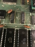
the CS2 signal is missing. I recognize a strange scratch on the board interrupting on of the lines. Not sure if it is the CS2 signal but it looks like it. I try to repair the connection.
Harald
 

Attachments

  • C6D899D5-34BB-4BFB-8624-AEDA9FAF651A.jpeg
    C6D899D5-34BB-4BFB-8624-AEDA9FAF651A.jpeg
    1.3 MB · Views: 20
Ah,

/CS2 is the main chip select from /SELE.

If this is missing, none of the big peripheral chips will be selected...

Dave
 
Hello Dave,

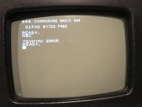
great, fix the interruption and got the blinking cursor back. I'm just surprised about the scratch because I didn't make it. maybe there was some connection at the beginning that was interrupted by the warmer circuit board.
Thanks for your help. I'm sorry that you spent a lot of time on my problem.
Now I can continue testing the tape drive. There is no end to the loading of a program.

Harald
 

Attachments

  • 577413BB-B8F8-4340-A79A-B5A6B3495A38.jpeg
    577413BB-B8F8-4340-A79A-B5A6B3495A38.jpeg
    1 MB · Views: 10
Harald,

Well done.

It’s great when a plan comes together!

I hope you have learnt a few of the tricks to fault finding on the PET.

The best way to fault-find sometimes is to use your eyes! But something as simple as checking that all the signals get from A to B is sometimes all that is required.

One thing I did notice was the excessive build-up of flux on some of the solder joints. You might like to consider getting some IPA (Isopropyl alcohol) and cleaning them up a bit.

If you have a tape drive it is worth getting it fixed of course so that the PET can load/save using it for authenticity.

You might also like to consider one of the PET SD card solutions that plugs into the IEEE488 port and provides for disk emulation.

You can then sit back and “burn it in a bit” by the playing of space invaders!

Dave
 
Well done Harald. Of course the main board still has RAM and possibly ROM faults but understandably you may not be concerned about tracking them down for the moment at least.

I had some fun and games with the datasette when refurbishing my PET so let us know if you run into any difficulties.

For now enjoy your working PET!

Alan
 
Back
Top