• Please review our updated Terms and Rules here

Cromemco JS-1 Joystick Replica

I've created a Mouser project for all the components needed for the PCB here: https://www.mouser.com/ProjectManager/ProjectDetail.aspx?AccessID=e130c7c33d - the quantities are for a single PCB

@Hugo Holden Would you mind taking a look at the chosen transistors in particular to make sure they match the specs we want? Thanks!

Mostly very inexpensive parts except for those tantalum caps.. Do you think an axial electrolytic could be substituted?
All the parts look ok, none are particularly critical.

On the topic of those 10uF axial Tant caps. Cromemco used them on the D+7A board. They have suitable electrical properties to act as the input and output filter caps on LM7xxx voltage regulator IC's. If using just electrolytics, it would pay to put 0.1uF ceramic capacitors in parallel with those so that the high frequency performance prevents the regulators from oscillating. In general for most of these regulators a 0.33uF capacitor is recommended on the input and output at least, many a case most manufacturers to keep it simple used 4.7 to 10uF Tants. In many a case they are bead types.

I'm not much of a fan of bead Tant caps, as they age they have a penchant for shorting out. The new ones are not as bad as the old blue and green and orange ones from the 70's and 80's, but with more time, who knows. I use the bead ones too, because I'm not a fan of electrolytic caps in general. If many cases now, with vintage restorations, where possible, the uF values and voltage value and physical size permitting, I replace electrolytics with film types. This eliminates the need for future replacements.

On the other hand, the mil spec axial Tants are super reliable and I have replaced many more electrolytics. I have not seen these types fail, even in a single case, in any of my vintage gear so I have more confidence in them. They were used a lot in Tek scopes and military VDU's. They have very good electrical properties, low ESR and very low leakage compared to an electrolytic. They never dry out or lose capacity. The have a sealed body with a glass seal at one end, unlike the electrolytic cap with a rubber bung that ultimately perishes. So with these axial Tants, I'm very fond of them, but, compared to an electrolytic cap, they are very expensive little devils.

Electrolytics are fine everywhere for this projects though, the Tants are not absolutely required. But if electrolytics are used on the regulator inputs and outputs, it might pay to parallel a 0.1uF monolithic ceramic capacitor with each one.
 
Thanks I just updated the project & ordered 2 sets, all parts <$18 shipped (choose economy shipping, it still always comes quickly).
 
Sorry, I haven't been keeping close track - am I drilling speaker holes in addition to the front panel?
 
I have some things to report:

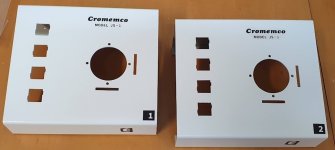
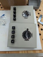
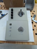
The duplicolor car touch up car spray paint is compatible with the Acrylic Decals, it is just in the first instance I applied too much of the thick coat because I wanted the decal to remain intact while doing the metalwork. With a light spray the decals are fine and the clear duplicolor strengthens the decal and makes it very scratch resistant. Without that the decal is very weak. The reason it reacts chemically is because the dupliclolor spray is an acrylic based product most likely, like the decal so its solvent reacts with it, but it is very fast drying.. It is definitely not enamel and won't dissolve in mineral turpentine (paint thinners in the USA). On the other hand Acetone dissolves it well. Duplicolor dries in 5 to 15 minutes. The duplicolor paint also allows the surface texture to largely remain. The main thing with the decal is to apply a relatively thin coat and don't over do it.

I was looking at the spray coat that Hammond had applied. They didn't do a very good job and there were blemishes at the edges with one case. But at least the paint adhesion to the surface is reasonable. In any event the color of it is more than off white, it looks to me more like a light grey with just a hint of yellow or green in it. I was looking at it and though, a good color for an undercoat perhaps. Then the penny dropped, I should re-coat that part.

On the other hand the blue part of the Hammond housing is very well done.

I spray painted painted with Duplicolor Arctic White DSN02, it is a Nissan "color". After that applied the decals the applied a coat of duplicolor clear DS117.

(I'm using a 9 pin connector on the rear of my units)

I should get the buttons/switches soon, hopefully this week, public holiday here today.
 

Attachments

  • casea.jpg
    casea.jpg
    80.5 KB · Views: 14
  • caseb.jpg
    caseb.jpg
    57.3 KB · Views: 14
Wow those turned out great! I was also thinking about respraying the white portion of the case to match the original better and cover the unfinished spots after cutting.
 
@nullvalue:

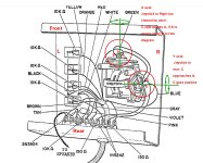
We know that the joystick outputs are supposed to be close to +/- 2V in each direction, though do we know for sure if they stuck to the Cartesian system. For example, if the stick is shifted towards the right on the x axis, does that result in a positive increase of the output from the x potentiometer and if the stick is moved upwards (away from the user) does that result in a positive increase from the Y axis pot. I just thought that could be worth checking on the original unit to be 100% sure.
 
We know that the joystick outputs are supposed to be close to +/- 2V in each direction, though do we know for sure if they stuck to the Cartesian system. For example, if the stick is shifted towards the right on the x axis, does that result in a positive increase of the output from the x potentiometer and if the stick is moved upwards (away from the user) does that result in a positive increase from the Y axis pot. I just thought that could be worth checking on the original unit to be 100% sure.

I could give this a test. But wouldn't the polarity just be based on which side I hooked the GND & +V to? In the unit I have, it was never built so one would have to look at the build instructions to figured out which way it's supposed to go.
 
I could give this a test. But wouldn't the polarity just be based on which side I hooked the GND & +V to? In the unit I have, it was never built so one would have to look at the build instructions to figured out which way it's supposed to go.
Yes, it would depend on what way around the outer connections of the pots were wired.
 
Hi,

On the JoyStick circuit board, if there are male PIN headers to connect to the JoyStick POTs, then it should be easy to configure/reconfigure when testing the JoyStick with software.

It's fairly easy to install 2-PIN male headers on circuit boards so each JoyStick POT would have two wires going down to the circuit board and probably just need to be rotated 180° during the testing.

or ... there might even be a couple of switches on the back of the JoyStick cabinet to allow reversing polarity so to accommodate other software that might work as reversed JoyStick operations.


.
 
Wperko:

The thing about these joysticks is that there are three ways the pot can be positioned:

1)The operator joystick
2) the fine adjustment user vernier which adjusts the offset
3) the Pot carrier which adjusts the global coarse offset.

If the pots ran off exactly the same + and - supply voltage then switch the +/- leads would have no other effect than flipping the polarity of the output.

But because of the coarse offset adjustment, if the leads were just switched around and because the + and - supply voltages don't exactly match, the magnitude of the + and - voltage swings from the pot would shift, one getting larger and the other smaller, it then requires that the coarse offset be re-set again to shift the pot to a different mechanical center.

It would be better to figure out from the info we have, which way Cromemco had it .
 
Looking at the diagrams, it appears highly likely that the chosen polarity matches the Cartesian plane, in that, from the user's perspective, a movement of the stick to the R on the X axis, results in a positive output, and a movement of the stick away from the user to the rear of the unit on the Y axis, results in a positive going output.

It is interesting that the console version that used the 100R speaker, it used +/- 12V supplies for the Joystick pots, which would have tended to make their outputs closer to +/- 2.5V , rather than +/- 2 volts when 10V and 12V supplies were used in the other units.

It might take a while to work out if some of the Dazzler programs might prefer a +/- 2.5V joystick output, rather than a +/- 2 volt output.
 

Attachments

  • Polarity.jpg
    Polarity.jpg
    275.5 KB · Views: 5
Last edited:
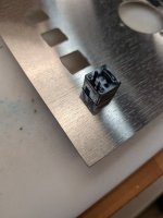
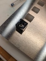
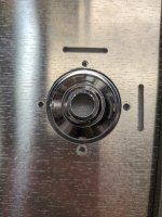
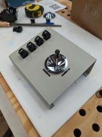
Well, the switch slots are spot on
1715447811904.jpeg
1715447827963.jpeg

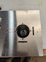
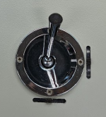
And the Joystick center holes are spot on

1715447873469.jpeg

But the trim lever slots are not.

1715447917376.jpeg

I'll monkey around with it a little bit.
 
Success.

1715456782022.jpeg
1715456797094.jpeg
1715456830498.jpeg

2 things I noticed.

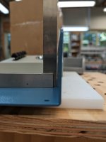
1) the blue base walls are not perfectly vertical - they splay out just a bit, so they'll need to be bent in a bit for the thing to fit together tight. I can try to bend them in but I'm a bit worried about marring the painted surface. Let me know.

1715456875691.jpeg

2) the Y return spring is missing on one of the joysticks, so it does not return to center. I can see if I have a similar spring in stock if you want, but you can also get them from Amazon pretty easily.
1715457001766.png

Let me know on the above issues, either way I'll put these in the mail on Monday.

Thanks,.
 
Success.

2 things I noticed.

1) the blue base walls are not perfectly vertical - they splay out just a bit, so they'll need to be bent in a bit for the thing to fit together tight. I can try to bend them in but I'm a bit worried about marring the painted surface. Let me know.

2) the Y return spring is missing on one of the joysticks, so it does not return to center. I can see if I have a similar spring in stock if you want, but you can also get them from Amazon pretty easily.

Let me know on the above issues, either way I'll put these in the mail on Monday.

Thanks,.

Dang that turned out great, thank you!! I did also notice that about the blue side walls not fitting well. I tried to bend them but it didn't seem to do much.. If you don't mind giving it a try, I would appreciate it. I understand there may be some paint risks involved. Thanks for the offer on the spring, but I already ordered one on eBay and they should be here in the next dew days.
 
Dang that turned out great, thank you!! I did also notice that about the blue side walls not fitting well. I tried to bend them but it didn't seem to do much.. If you don't mind giving it a try, I would appreciate it. I understand there may be some paint risks involved. Thanks for the offer on the spring, but I already ordered one on eBay and they should be here in the next dew days.
Interesting that. One of my Hammond cases had the same problem with the side walls. I used my bench folder to steepen the bend, that is ok if you protect the painted surface with tape. Also there was a subtle concave curvature of the base that aggravated the problem.

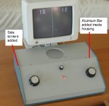
This is not the only time I have seen this problem in this sort of format Hammond case. When I used a larger one for a mini-Pong project it was necessary to fit a 3/8 x 3/8" aluminium Bar to cross the inside of the cabinet and threaded with holes at each end, so side screws could be used to pull the side walls inwards. But in these smaller Joystick enclosures, there is less room for this sort of thing.

(You never get these sorts of issues with Takachi enclosures, because the Japanese are perfectionists).
 

Attachments

  • Bar.jpg
    Bar.jpg
    98.9 KB · Views: 6
Back
Top