• Please review our updated Terms and Rules here

DEC H780 Supply Caps

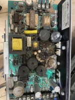
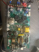
I tested, reformed, and where necessary replaced the large electrolytic caps in my 34A. Next time it moves onto my front burner, I guess I should go through the power supplies again and look more closely at the smaller electrolytic caps, too. The photos in this thread may give me nightmares involving the fishy smell of leaking electrolyte. 😬
 

Thanks!

The bracket is just noted as a customer-installed part and is not dimensioned, which is why I don't know exactly what size it's supposed to be :p

Aha. I see. If you come up with something I am interested!
I can get a picture on the RKV11-D but IIRC my QBus BA11-M is missing it also. It looks like the RKV11-D may be different, but I'm not sure as neither of mine have covers!


I guess...but won't you be driving current sense elements backwards? With current limiting it probably prevents anything catastrophic from happening. And it still doesn't help with the DC bulk cap, so you're still either opening the supply to reform out-of-circuit, or bringing it up on a variac (not always a good idea on some switcher topologies).

But since we are driving current backwards the rectifier diodes will block. No current will flow. Except for initial current when the caps charge. I really like to test the crowbar so I am sure that it will trigger if the control circuitry fails. I have seen bad zener dioded and want to make sure it works. A current limited supply make sure no damages is done.

With separate power to the control circuitry I can verify that it operates correctly as I slowly get the voltage on the outputs to the nominal voltage. The switching pulses will quickly go from max to min now.

The input bulk caps has to be dealt with separately. Since I usually drive the control circuitry with a external PSU i can ramp up the input AC through a variac ( an inline incandescent lamp is a good safety measure if something short circuit). In this way I sort of reform the input caps.

Actually current sense on the outputs is something I seldom test separately. Never actually needed to do that. Current sense is mostly a resistor and a comparator. Don’t think they are easily damaged.

I test with dummy loads and don't usually try and trip the crowbar.
Yes. I have various dummy loads to test the PSU with.

Last repair. Before and after. Used to be a mouse toilet…

IMG_3684.jpeg

IMG_3997.jpeg
 
I had the same with my low profile PDP11/34 and its H777 power supply. I never switch on these things before checking the mains circuit and power electronics. I ended up replacing all 14 electrolytic capacitors. But it was rewarding to have a working PDP11/34 :love:

I had a few in the modules in my PDP-11/34a's H765 regulator modules as well.
 
>>> Can you explain for me what “back feed” means?

It means to connect a power supply 'backwards'.

What I mean by this is you keep the input to the power supply disconnected and feed the output(s) from a current-limited supply of a lower voltage than the power supply outputs, and then slowly ramp up the voltage to the specified power supply output voltage for the rail.

The large smoothing capacitors are usually on the output side of a power supply, so by feeding the power supply this way you can usually test and reform the electrolytic capacitors without removing them.

Like everything, this may only work under certain circumstances. We use a lot of power supplies where they have output diodes (blocking diodes) so we can parallel them up (for redundancy purposes). In this case, this scenario would not work (the blocking diodes will be preventing the requisite current flow). However, if you already know this, you can put a red shorting link across the blocking diode and it will work. The wire colour is not important of course (!) it just stands out so you remember to remove it before using the power supply...

Having the schematic diagram for the piece of equipment to hand, and looking at the options available to you, can prevent a lot of disassembly work when testing and reforming power supplies.

Does this make sense?

Dave
Yes, makes perfect sense, thank you for you elaborate answer 😃👍🏻
 
You 'should' be able to do one at a time, but there can be some 'gotchas' with this.

You can only really ascertain this on a case by case basis after checking the schematic.

Dave
 
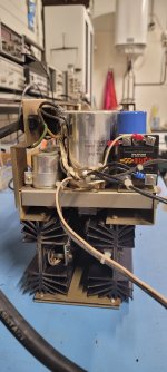
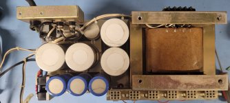
I'm working on a PDP11/03, and after some digging I was able to get the power supply out of the case, and I must say it looks remarcably clean. No mouse droppings or whatever.
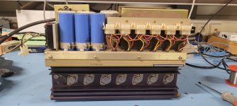
20241009_095028.jpg
Overkill if you ask me, looking at the number of boards and the size and number of power connectors on the supply.
So before anything else I had to inspect the caps for leakage and polarity.
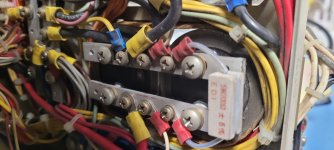
20241009_114624(0).jpg
Not an easy task, I was able to remove one capacitor so I could check the polarity, inspect for leakage (it looked great!) and apply voltage to it to see what happens to it when I do.
Nothing happened which is great 😄
This made me confident to take the next step: using a variac to slowly increase the mains voltage.
On the side of the power supply there sits a solid state relay, but since I took the supply out of the case, the on/off switch is detached, so I replaced the switch with a piece of wire.
And reading that I should never switch on a power supply without any ventilation, even when I do not draw any power from it, I took an old 12 volt computer fan and attached it to the heatsink.
I slowly increased the main voltage with the variac while keeping an eye on the voltages on the power connector used to power the system.
The voltages slowly increased as I turned up the variac, kept it for about 10 minutes before increasing about 30 volts at a time.
I noticed the 15 outlet was about twice the 5 volt pins on the connector so I figured that was okay.
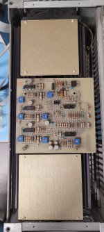
20241009_093112.jpg
Also the three LED's on the righthand side of this board started to emit red, so all's well.
But at some point when the 15 volt pin was a few volts, suddenly the voltage drops to zero and the LED's went dark 😱
I repeated the procedure, turning the variac slowly up until the LED's go out, and I noticed that prior to the voltage drop two leds on the board flashed.
These LED's are marked: DC LO and AC LO.
That made sense! At a certain voltage the power control circuit begins doing its thing and detects a low DC and a low AC, which is considered a faulty condition and the power shuts down.
Coming to this conclusion and no magic smoke coming from the supply I was confident enough to yank the variac to 230 volt output, and there was a working power supply
🍾😄🍷
 

Attachments

  • 20241009_095055.jpg
    20241009_095055.jpg
    903.8 KB · Views: 12
  • 20241009_095034.jpg
    20241009_095034.jpg
    1.8 MB · Views: 11
Back
Top