VERAULT
Veteran Member
I have been putting this off for a while because of the condition of this unit. I picked it up a couple years back with my Cromemco System One: https://forum.vcfed.org/index.php?t...s-of-waiting-and-searching-i-got-one.1240316/
Initial photos of the Drive unit can be seen here: https://photos.app.goo.gl/xXfKznfZAzNQ7H4m9
So the reason I have put off this repair/restoration is this drive was completely filled with vile rodent filth. It was disgusting in every way. When I first got it home I had to vacuum out a huge nest with several dead mice inside long since dead. The excrement and urine had caused huge amounts of corrosion and some wires were chewed through and would need repair. Because of its condition I couldnt bring it in the house until it was time to repair it. Strange the Other items in the pickup were fine. I guess because they were closed for the most part and these two large floppy drives were left open and it is a massive unit pretty welcoming to rodents.
Its initial condition was enough to make most people pass or throw it out.. But a Dual QUMETRAK drive isnt exactly common so its definitely worth a good attempt.
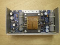
This restoration will have to be done in stages so lets first tackle the power supply. I took it completely apart to wash the boards of urine and clean up as much corrosion and rust as possible.


This power supply has a date code of December 17th 1982. It contains a rusty large transformer and a left and right circuit board. The left board was in far worse shape as it had a nest directly in it.
The left board is marked 50364C And contains two Motorola 10261 223 transistors at Q1 and Q3.
It also has two socketed LM723 voltage regulator IC's. The sockets are in sad shape so I installed new ones. The left LM723 was so corroded a few legs fell off. So I purchased some replacements: https://www.ebay.com/itm/291717373259
I also replaced all the smaller Electrolytic capacitors on both boards. And let me just say, I am sure noone enjoys doing a recap job with leaked electrolytic as it has a fishy smell. However even after two washes and lots of rubbing alcohol (BECAUSE IPA IS A BEER!) the smell of burning hot urine is just the worst thing!
There are 3 adjustment pots, 15V adj., +5v adj, and I. Limit. So I am assuming I. Limit changes the level of Current.


The right board is marked 50362B. It had one LM723 soldered directly to the board so I removed it and socketed it. Again, I replaced all the smaller electrolytic caps on this right board. It has a variable resistor which is marked 24V adj. and another marked 24V I. LIM. Also assume the I. Lim. adjusts the level of current.
So I am guessing that the board on the left is for 5V and the board on the right is for 24V (no 12V?).
Q1 on the right board was so corroded, after wire brushing it off there is nothing left to show what the component is except "221" stamped onto it. So this part is a mystery although my component checker states all 3 are acting correctly as transistors.


Is anyone familiar with this model or brand of Power supply boards from the early 1980s? Are there possibly Schematics or documentation on them out there?
Here is a photo of the transformer. And I guess thats it for now. I can do some testing once the LM723 ICs come in the mail. If anyone has anything to add please feel free. This is be a big undertaking.

Initial photos of the Drive unit can be seen here: https://photos.app.goo.gl/xXfKznfZAzNQ7H4m9
So the reason I have put off this repair/restoration is this drive was completely filled with vile rodent filth. It was disgusting in every way. When I first got it home I had to vacuum out a huge nest with several dead mice inside long since dead. The excrement and urine had caused huge amounts of corrosion and some wires were chewed through and would need repair. Because of its condition I couldnt bring it in the house until it was time to repair it. Strange the Other items in the pickup were fine. I guess because they were closed for the most part and these two large floppy drives were left open and it is a massive unit pretty welcoming to rodents.
Its initial condition was enough to make most people pass or throw it out.. But a Dual QUMETRAK drive isnt exactly common so its definitely worth a good attempt.
This restoration will have to be done in stages so lets first tackle the power supply. I took it completely apart to wash the boards of urine and clean up as much corrosion and rust as possible.
This power supply has a date code of December 17th 1982. It contains a rusty large transformer and a left and right circuit board. The left board was in far worse shape as it had a nest directly in it.
The left board is marked 50364C And contains two Motorola 10261 223 transistors at Q1 and Q3.
It also has two socketed LM723 voltage regulator IC's. The sockets are in sad shape so I installed new ones. The left LM723 was so corroded a few legs fell off. So I purchased some replacements: https://www.ebay.com/itm/291717373259
I also replaced all the smaller Electrolytic capacitors on both boards. And let me just say, I am sure noone enjoys doing a recap job with leaked electrolytic as it has a fishy smell. However even after two washes and lots of rubbing alcohol (BECAUSE IPA IS A BEER!) the smell of burning hot urine is just the worst thing!
There are 3 adjustment pots, 15V adj., +5v adj, and I. Limit. So I am assuming I. Limit changes the level of Current.
The right board is marked 50362B. It had one LM723 soldered directly to the board so I removed it and socketed it. Again, I replaced all the smaller electrolytic caps on this right board. It has a variable resistor which is marked 24V adj. and another marked 24V I. LIM. Also assume the I. Lim. adjusts the level of current.
So I am guessing that the board on the left is for 5V and the board on the right is for 24V (no 12V?).
Q1 on the right board was so corroded, after wire brushing it off there is nothing left to show what the component is except "221" stamped onto it. So this part is a mystery although my component checker states all 3 are acting correctly as transistors.
Is anyone familiar with this model or brand of Power supply boards from the early 1980s? Are there possibly Schematics or documentation on them out there?
Here is a photo of the transformer. And I guess thats it for now. I can do some testing once the LM723 ICs come in the mail. If anyone has anything to add please feel free. This is be a big undertaking.
Last edited:
")