• Please review our updated Terms and Rules here

Dual 8 inch QUMETRAK 842 rack mount floppy drive restoration

Awesome! I've got some but I'd rather not part with them. Still, I want to see this beast live again!
Well i got s few 8" machines now.

Trs-80 model II
MAI Basic Four.
IBM 5120

And now these two Qumetrak drives which came with my Cromemco System One. So I bought up 8 inch disks whenever I could.
My hope is to use this dual drive setup to make disks for all these systems.
 
I have a specific pension for rack-mounted hardware, though; so seeing a rack mount 8" floppy system run tickles me fancy.
 
Well I put it all back together. Re-soldered in the transistors. But Im tired, and I just ripped a deer tick out of the skin on my rib cage so this will have to wait until morning...
 
Ok I have had some time today to re assemble and test.

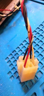
First off I discovered some more mouse chewed wires on the power connectors. I de-pinned them and slid on some heatshrink tubing to repair in 3 places.
IMG_20240411_113706.jpg

I Also replaced the IEC 3 prong plug on the end as the shielding had pulled away from the main body of the plug. I installed universal plus with LED so at least Id know when it was getting power.

I went over all the connections to make sure they were correct and powered the unit on.

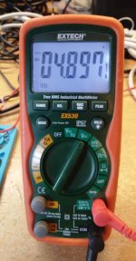
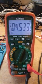
On first test of the 5V rail I got this: Only a little off so I adjusted the 5V adj pot.
IMG_20240411_120533.jpg

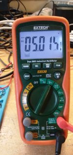
Then the 5v was spot on

IMG_20240411_120627.jpg

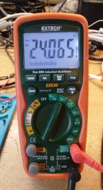
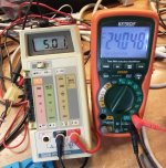
Next I checked the 24V rail. I did nothing to it at all and it was spot on. I couldnt believe it.
IMG_20240411_120737.jpg

The -5V rail (which I believe is NOT used in this QUME drive assembly at all) was low even after adjusting the 5V rail.. Just thought it was worth mentioning.

IMG_20240411_120825.jpg

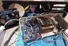
Next I added the 160MM AC fan back onto the system. At first I thought there was something inside the fan making a grinding noise but I realize I was rubbing. The fan pulls so many CFM's its a bit loud. But not loud because of bearing noise. Its just really really powerful. Its just a loud hum so inside the chassis it should be much better.

As you can see I cleaned up alot of corrosion. I wire brushed the transformer and wiped it with machine oil.

IMG_20240411_122559.jpg
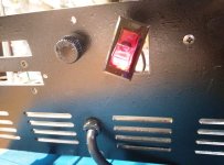
I was also happy to see the unmarked power switch had a working lamp in it so at least I would know which way was on.
IMG_20240411_121710.jpg

Note: all my initial testing was done without the fan and I noticed no humming from the Transformer.

I have the system running now (about 40 minutes straight so far. No change in voltages. I realize its not under load. I will check the Current and voltages again when I apply a load. For now im pretty happy with it.
I noticed the large caps I did not replace are working quite well. The 24V rail takes almost two minutes to deplete without a load.
IMG_20240411_122506.jpg

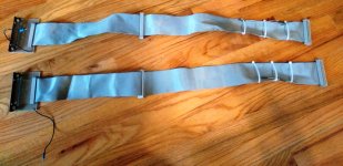
Truth be told before even working on the PSU I repaired the damaged wires to the data cables. One ribbon had 3 wires chewed through, another had one. Also One had a ground lug torn off.

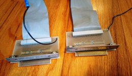
What I dont understand and I hope someone can clarify is why there are two ribbon cables (each with secondary connector) running to each drive with a card-edge connector on the back? Why is the secondary drive not connected to the middle connector? Wouldnt that be a better configuration for my needs going forward?

IMG_20240411_131421.jpgIMG_20240411_131433.jpg

So my thoughts on this PSU after all of this.. Power-one really must make one hell of a good PSU. I'm not big on before and after photos so just take my word this was a 10 on the awful spectrum. It had had stalactites of mouse urine and extremem corrosion. I washed the psu boards twice! I really wanted the acrid urine smell and filth gone. I really had mixed hopes of whether this was ever going to work again considering the open top PSU was a complete rodent nest.

I cant believe how little this psu took to get back up and running. A cleaning. A recap of the low-voltage caps, some wire repair, 3 new IC sockets, and one replaced IC that had corroded badly. Thats practically maintenance let alone a repair.

I know this is all still early and we havent gotten to the 8" drives yet.. But we will very soon.
 
I suspect that the cabling was a way to standardizing 1 and 2 drive installation, without having to resort to modifying the cables themselves. Note the jumper areas on the edge connectors. That being said, I've always used a single (flat, no twists) ribbon on my 8" 2-drive setups. Just set the DSx on each drive and you're done.

Linear power supplies are extremely reliable in general. Been around since they were "battery eliminators".
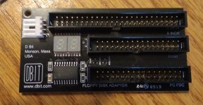
Well Id like to reuse these ribbon cables. I may need to re-jumper them. Im honestly not even sure how this was connected to my Cromemco. Or if it even ever was apart of it. But My first goal would be communicating with it via kryoflux and greaseweazle. Meaning Ill need to make a connector which is cardedge socket to 50 pin idc to connect to my DBIT 8inch drive adapter.
IMG_20240411_135625.jpg
 
I don't bother with the Dbit thing myself. The 842 doesn't use the TG43 signal, so there's no need for one. Just terminate a 50 wire cable to a DC-37 connector.
 
Well Ive got some learning to do on 8" drive signalling.
Generally, the idea of using 5.25" signals is to use the 5.25" signal names, with the exception that MOTOR ON should go to HEAD LOAD. Everything else should be pretty much the same. What you want to do with READY depends on the host side. Termination is the same (150 ohm pullup on one of the drives).

Some drives have index separators on them such that 32-hard-sector floppies will result in both an INDEX signal and a SECTOR signal (with no INDEX). Some also include dividers to simulate 16 and 8 sector floppies. Haven't glanced at the 842 doc in years, so I don't recall if it's one of those.

There's a lot of variety in 8" drives, but then it figures, as the industry was just developing. For example, NEC drives include PLLs for data separation. Calcomp drives used 40 pin Berg headers, etc. Then there are the older IBM drives that require external 3-phase signals for positioning.

And we won't talk about the Memorex 650 drives...
 
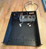
I gave the panels another wipe-down with really highly scented surface cleaner (as there is still the faintest smell of mouse urine after vigorous washing with hot water and tons of scrubbing and soap for some odd reason) and but the chassis back together panel by panel.. Next step the worse looking of the two 8" drives.

IMG_20240411_161218.jpg
 
Last edited:
I'll bet the TO-3 power transistors are 2N3055's, I have a 4 slot S-100 rack that had a small linear power supply board just for the two 8" drives. That supply had 2N3055's mounted to the main case more or less like your power sup;ply used the case for a heatsink. Your supply is a notch or two up in sophistication, as mine had no protection circuits - just a regulator IC for the 5 VDC and a zener for the 24 volt side. It failed and smoked the 8" drives and I replaced it with a Meanwell.
 
Back
Top