in2oblivion
New Member
- Joined
- Oct 1, 2022
- Messages
- 1
Hi - I started out with a QX-10 back in1981 and enjoyed using it and learning about how it worked. Even though I gave mine away years back, I provide tech support for a lawyer that still uses his to this day. After 37 years his monitor finally stopped working. I bought a used monitor off eBay but its display was quite shaky so I returned it for a refund. So now I needed some kind of replacement. I decided to purchase an XVGA Box (GBS8219) from Amazon and an 8-pin male connector from my local electronics store. As is the norm, the XVGA Box manual sucked and the color coded wires on the cable supplied didn't match the colors they had in their manual. So if you are going to attempt this setup you best have some skills with a multimeter and soldering, as well as a bit of patience.
I used the multimeter to test the continuity of the 9 wires coming from the DB9 male cable supplied and wrote down what the colors were for the 9 pins. Usually the connector has pin numbers molded into the plastic connector near each pin so you can keep track of them. Checking the QX tech manuals I found the pinouts for the 8-pin DIN connector on the back of the QX-10's CPU. With this info the cable can be wired-up so it will work properly. For the QX-10 the following connections are needed:
QX-10 | DB9
Pin # | Pin #
-------------------
2 --------- 2 = ground
4 --------- 8 = H.sync
5 --------- 9 = V.sync
7 --------- 1 = ground
8 --------- 4 = video signal (green)
FG --------- FG = frame ground
Once the cable is soldered and assembled it can be connected between the QX-10 CPU and the XVGA Box. Then attach any VGA monitor (CRT, LCD, etc.) to the XVGA Box and the 12V AC adapter to some power. Now you can power things up. I first turned on the XVGA Box followed by the QX-10 CPU and finally the VGA monitor. Don't be surprised if the display looks a bit blurry at first, but you should hopefully get something to display as long as the cable was made correctly.
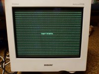
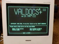
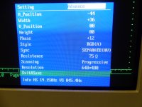
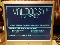
Once you see an image it's time to fiddle with the menu settings on the XVGA Box as well as on your monitor. This can take a fair amount of time, but in the end the display is pretty good as you can see in the pics. The best tip I can give for this is to adjust the screen as large as possible and then look for a doubling of the individual pixels in text displayed on the screen. I first used the horizontal options to make further adjustments (usually making it smaller) until the letters look good in the horizontal direction so that each character is illuminated and fully formed. Initially there appears a light and dark 'banding' that runs across the screen. As you make adjustments your goal is to reduce and eliminate that. Once the characters look good from left to right, then use the vertical adjustments on the XVGA Box to adjust it until the characters display clearly. While you're doing this you will also need to adjust the horizontal and vertical settings on your monitor. So you'll be adjusting both at the same time until the screen appears clear and is centered on the display. A final option to adjust is the phase. Not sure what it does, but it seems to shift that banding somewhat. Once the settings are saved you just turn everything on to use the machine and later turn things off when you're done. The first 2 pics show a Sony Trinitron CRT with the BIOS Boot screen and Valdocs loaded. Third pic shows the XVGA Box OSD settings and the last pic is an HP LCD monitor with Valdocs loaded.
I used the multimeter to test the continuity of the 9 wires coming from the DB9 male cable supplied and wrote down what the colors were for the 9 pins. Usually the connector has pin numbers molded into the plastic connector near each pin so you can keep track of them. Checking the QX tech manuals I found the pinouts for the 8-pin DIN connector on the back of the QX-10's CPU. With this info the cable can be wired-up so it will work properly. For the QX-10 the following connections are needed:
QX-10 | DB9
Pin # | Pin #
-------------------
2 --------- 2 = ground
4 --------- 8 = H.sync
5 --------- 9 = V.sync
7 --------- 1 = ground
8 --------- 4 = video signal (green)
FG --------- FG = frame ground
Once the cable is soldered and assembled it can be connected between the QX-10 CPU and the XVGA Box. Then attach any VGA monitor (CRT, LCD, etc.) to the XVGA Box and the 12V AC adapter to some power. Now you can power things up. I first turned on the XVGA Box followed by the QX-10 CPU and finally the VGA monitor. Don't be surprised if the display looks a bit blurry at first, but you should hopefully get something to display as long as the cable was made correctly.
Once you see an image it's time to fiddle with the menu settings on the XVGA Box as well as on your monitor. This can take a fair amount of time, but in the end the display is pretty good as you can see in the pics. The best tip I can give for this is to adjust the screen as large as possible and then look for a doubling of the individual pixels in text displayed on the screen. I first used the horizontal options to make further adjustments (usually making it smaller) until the letters look good in the horizontal direction so that each character is illuminated and fully formed. Initially there appears a light and dark 'banding' that runs across the screen. As you make adjustments your goal is to reduce and eliminate that. Once the characters look good from left to right, then use the vertical adjustments on the XVGA Box to adjust it until the characters display clearly. While you're doing this you will also need to adjust the horizontal and vertical settings on your monitor. So you'll be adjusting both at the same time until the screen appears clear and is centered on the display. A final option to adjust is the phase. Not sure what it does, but it seems to shift that banding somewhat. Once the settings are saved you just turn everything on to use the machine and later turn things off when you're done. The first 2 pics show a Sony Trinitron CRT with the BIOS Boot screen and Valdocs loaded. Third pic shows the XVGA Box OSD settings and the last pic is an HP LCD monitor with Valdocs loaded.