• Please review our updated Terms and Rules here

First post and TRS-80 question

dutchacorn

Experienced Member
Joined
Oct 7, 2015
Messages
85
Location
Netherlands
Hi!

I'm Paul from the Netherlands and my retro-madness started when I bought an attic full of eighties Acorn hardware & software. That's also when I first discovered retro forums - hence the user name.

In my forties now, I grew up with the British computers (Sinclair and Acorn) in the eighties. Also some C64 memories. Young kids, an understanding wife (within reason) and a more and more cramped study.

In retro land I'm a jack-of-all-master-of-none type with a preference for hardware.

My older brother mentioned the Exidy Sorcerer which I managed to get (looking for a S-100 interface). And, treading into the pre-1980 CP/M computer era, this Monday I got a TRS-80 with expansion interface and drive but no display or connecting cables (still looking for cables). The TRS-80 works (except the LED :shock:), the drive works, no idea about the expansion interface yet. Fixed up a video cable.


The previous owner fixed an extra DIN plug to the TRS-80.
IMG_3510.jpg

Any ideas what it can be for? My initial thought was an RGB plug but for a B&W computer?

Many thanks,
Paul
 
... your photo's too low res for me to read the labels on the board, can you post a bigger one or say what devices the wires are tied to? (IE, look for the "Zxx" for the ICs, "Q" for the transistors, etc.) I'm going to take a really, really wild guess here: Looking at the schematic there's a transistor Q2 that seems to be involved in mixing the Sync signal with video to produce the composite output. I'm going to make the wild guess that the other solder point connects to the raw video output also upstream of the mixing circuit and therefore this pigtail was designed to allow the hookup of a TTL digital monitor. I vaguely recall a plan for doing just that appearing in an issue of 80 Microcomputing at some point, it would make for a substantially clearer picture than the original modified TV.
 
The extra DIN connector is for the Expansion Unit. It is known as the "DIN cable modification" (appropriately enough!).

I don't think that's what it is. Notice that the connector is routed out between the cassette and power plugs; the DIN mod was always routed out next to the 40 pin expansion connector. Also pretty sure you're not going to find the CAS/RAS signals next to a transistor like that.
 
I think it's a Japanese board. At the lower right corner of the picture it says "ROM Z42", which fits with the Japanese board having ROMs at Z42 and Z43 (according to the Dutch TRS-80 users group hardware manual), rather than ROMs at Z33 and Z34 as on the U.S. board (1700069).

The green wire is connected to Z5 pin 8, which (on the Japanese board) is HDRV (i.e., horizontal sync), which matches Eudimorphodon's theory that this is a cable for connecting to a TTL monitor.

Btw, Ian, do you have a PDF of the service manual for the Japanese systems (26-1003A et al.)? I can't find it online anywhere.

And Paul, is there any chance you could post pictures of each side of the board, with enough clarity that we can read the labels on the board and on the chips? That would be helpful for people trying to identify Japanese boards and components.
 
Hi Petrofski, I have a PDF of the manual... It's not bad but the schems are hard to read because they were taped together, and the tape went brown. But there should be enough information for Japanese M1 owners.

I've emailed you the PDF.

Ian.
 
...
And Paul, is there any chance you could post pictures of each side of the board, with enough clarity that we can read the labels on the board and on the chips? That would be helpful for people trying to identify Japanese boards and components.
Well, I got a bit distracted :rolleyes::oops:
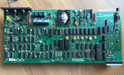
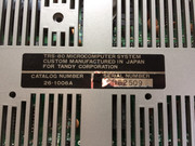
, but yes, it was a Japanese TRS-80 and here's a picture of the PCB ...

PCB.jpg
 
Thanks!
Unfortunately, I can hardly read anything in that pic. I'm guessing your image is actually good enough for things to be readable, but when you uploaded it it was trashed by this board's ridiculous image-crapifying feature. Can you post a good copy somewhere else, like imgur.com?
 
How about this one:


Of course the "Made in Japan" is also quite hard to miss...


Apart from the crisp quality of the lettering on the PCB one very noticeable difference with the US model is the better display quality of the Japanese made model.
 
I hope this works better:


But the "Made in Japan" next to the serial number is quite obvious...


Apart from the clearer lettering on the PCB the other main difference between the US and the Japan produced version imo is the much better video quality on the Japanese version.
 
Yeah the Video chain has less logic chips in it as well. Edit same with the CPU side of the board.

That looks much more like a Model III, notice only two video ram chips, but it does have the 6673 char generator of the Model I.

And a CGA socket....
 
Last edited:
That's pretty interesting. What's the story on the Japanese Model I? It's curious that the improvements never made it back to the US Model I.
 
I wrote about the Jap M1 in a long article in TRS8Bit newsletter, June 2016. I can only speculate but knowing how Tandy likes to cost-reduce a successful product, the Jap M1 looks like a TEC cost-reducing project aimed to allow RS to sell the M3 alongside the cost-reduced M1. To do this the manufacture of the M1 would need to be moved overseas (Japan, by TEC) and the M3 made in Fort Worth. The FCC killed the M1 and I reckon TEC had already put the Jap M1 into production and made some 20,000 of them before Tandy could cancel the order, so those machines pushed onto other markets like Australia, UK, EU and Japan. It explains why the M1 was available in Australia and the UK/EU until mid-1983 even though it ceased being available in the US by the end of 1980.

Like I say, I can only speculate and would only be able to find out if this was indeed fact by asking John Roach, Bernie Appel or Ed Juge. And we're a bit late for that.
 
That sure does look like a better build quality and while it may be less components there is clearly some improvements made.

I'm assuming that CGA is alternate character generator. Curious how they held up, have you ever had to work on any Ian to judge if its an improvement?
 
That sure does look like a better build quality and while it may be less components there is clearly some improvements made.

I'm assuming that CGA is alternate character generator. Curious how they held up, have you ever had to work on any Ian to judge if its an improvement?
The CGA is for the Kana (Japanese) character set.
 
Tibs, in Australia its actually the most desirable Model I for end users who don't wish to modify their machines. The jap has rock solid display (no shimmer), ALPS keyboard, lowercase from the factory, and improvements carried over from the Model III (2112 video rams and much less sensitive cassette loading), un-pluggable keyboard, and in fact I've never had one in for repair other than people plugging the power into the video or cassette socket.

Drop in the CGA char-gen and fit a japanese Kana alps keyboard and you can switch between english and kana.
 
Back
Top