• Please review our updated Terms and Rules here

Four-voice polyphonic music on my S-100 Z80 system circa 1981-1982

1944GPW

Veteran Member
Joined
Apr 26, 2011
Messages
810
Location
Brisbane, Australia
A long time ago I was a Sydney schoolkid who had an australian Applied Technology S-100 system which my brother and I built from a series of kits. It comprised a DG680 CPU, ETI-640 VDU, ETI-681 PCG, and I honestly can't remember how much memory but it was a few 16k boards of static RAM, so most likely 64k. As well as a nice black aluminium card cage with a beefy transformer and caps, and loading/saving to a cassette tape recorder. Later on we got a Versafloppy II and a TEAC FD-50A (but no operating system, started writing my own) but that's another story.

After reading the brilliant article 'A Sampling of Techniques for Computer Performance of Music' by Hal Chamberlin in the BYTE September 1977 issue one of the things I wondered was, could my Z80 also generate polyphonic music in real time:
https://archive.org/details/byte-magazine-1977-09/page/n63/mode/2up

Hardware.
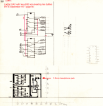
Firstly I made a little etched PCB for the circuit on page 66 of the article. This is a simple 8-bit ladder DAC using two CMOS 4050 non-inverting buffers with a bunch of resistors. I most likely got the components from the Dick Smith store on the Pacific Highway in North Sydney, who actually had really good hobbyist electronics items at that time.
8-bit_ladder_DAC_board.png

It's all so long ago now but I think my PCB below combined that circuit with the transistor amplifier on page 77. But given that the LM3900 is a 16-pin device and I seem to have an 8-pin amplifier chip drawn there, I'm baffled now. Maybe it was an LM386 or something, I can't recall. The BYTE article has a further circuit for a low-pass filter but I didn't bother with that and just amplified the DAC output directly.
The board had a mono headphone jack which I fed into my AKAI AA-1050 stereo receiver perched along with a pair of JVC SK-33 speakers on the top of a piano in my bedroom. The DG680 CPU board had I recall a 16(?)-pin DIP socket on it for at least one Z80 I/O port. Anyway I soldered a ~30cm length of ribbon cable to a DIP header for this, and the other ends soldered to the DAC board.

Software.
Alas the article's examples were for a KIM-1, and the 6502 instruction set was a bit too 'alien' for my 'Z80 brain' so a very clever school friend of mine who knew his Apple ][ inside and out translated the examples into Z80 code for me (without even knowing or being interested in the Z80 architecture as it was too 'baroque' compared to the 6502 he thought), and I present his code here along with my own annotations and further experiments. I haven't seen hime for maybe ~40 years now as he moved to the US but I suppose he wouldn't mind me putting this on the net for others to enjoy and learn from like I did.

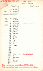
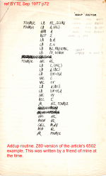
This is his original code for the two routines. The ADDUP routine calls the PLAY routine which in turn does the summation of amplitudes of the four voices and sends the value in the accumulator to the DAC on I/O port 2.
Z80_four_voice_PLAY_routine.png


Z80_four_voice_ADDUP_routine.png


Also for some reason I had a version of this Play routine which is mostly the same as my friend's version but I can't see any tempo logic there.
The two columns at right are the intruction execution times for each instruction + opcode in uSec, one for running at 2MHZ and the other for running at 4MHz, explanation below.
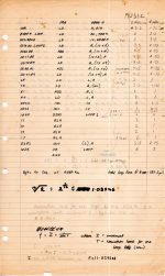
my_notes_1.png

Also the integer cosine table needed for the lookup and summation of the (up to) four voices as the waveform was being synthesised, this lived at 6100H.
Each voice went from 0 to 3F so the four together would be FF ie the full eight bits for the DAC:
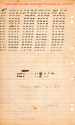
my_notes_2.png


I annotated the musical note table from page 76 of the article for a 4MHz Z80. This was at 5300H, looking at my annotations to my friends ADDUP code.
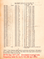
Z80_4MHz_note_frequency_table_annotated_BYTE_Sep_1977_p76.png

Now for the musical score to be played. I had no idea what the article's 'Star Spangled Banner' example sounded like so I typed in some or half of it to test it out. It worked so I took one of my Mum's piano scores (hence the piano in my bedroom) and encoded Bach's Praeludium in C Major, one of my favourite classical pieces at the time. Unfortunately I don't have the notes or scribblings for that to present here but undoubtedly it would have been scribbled out on a piece of Foolscap paper like the above. I did start writing a simple musical note editor for further easy score encoding but never finished that.

Further note: I had modified my DG680 Z80A CPU board to have a double-speed 'turbo' mode, this was a 4MHz crystal glued to the solder side of the card near the top edge along with a cool blue rocker switch salvaged from some IBM junk. Thus I could go from 2MHz to 4MHz and it was a real performance improvement. Sometimes if I was lucky I could switch from 2 to 4 without the program crashing, and it would continue to run, probably helped by having only static RAM I guess. Otherwise it just needed a reset after switching. I think I needed to switch back to 2MHz to load/save from tape, but I can't recall now.

In the course of writing up this memoir I browsed through Hal Chamberlin's opus 'Musical applications of Microprocessors' but to be honest the details about real-time waveform encoding are really buried in there along with a heap of other technical mumbo-jumbo, so I recommend the BYTE article over the book if you just want to experiment without getting into too much complexity. It does however go into detail about NOTRAN, Mr Chamberlin's score notation encoding program, and maybe that would be good to re-imagine for a modern Z80 project.

Anyway that's all I can remember about this project from long ago, hopefully I've described enough here for VCFED folks to perhaps get their old Z80 box to do a new trick.
 
This is a wonderful article.
Your system most likely comprised of 48K being 3 x 16K TCT or AT16K memory cards with DGOS residing at the default D000-D7FF, onboard scratch RAM at D800-D7FF, VDU at F000-F7FF and PCG at F800-FFFF.
It is possible to have an additional 4K of RAM at C000-CFFF on a 4K or partially populated RAM card for a CP/M usable 52K system.
This leaves a hole at E000-EFFF to accommodate a 2-4K Disk Controller ROM.
The DGZ80 has a PIO and 2 user I/O ports with one used used with a parallel ASCII keyboard and the other with PIO PortB and some CTC I/O pins.
It also has an 8 bit input sense port near the TO-3 5V voltage regulator.
For the system to run reliably at 4MHz all of the RAM and ROMs needed to be upgraded to 300ns access time minimum which was a very expensive upgrade at the time but many enthusiasts took the punt and used the more common slower 450ns access time memories.
Your cassette interface was either an USCI or modified SECI with timing generated from the DGZ80's CTC so as an alternative to changing the CPU clock speed one could use a DGOS ROM assembled for 4MHz operation.

Your program would work on a microbee with adjustments to operate with a 2 or 3.375Mhz CPU clock.
 
That is a really interesting article (both the Byte article and your conversion from 6502 to the Z80).

Thank you for sharing.

I started buying Byte magazines 'sporadically' at that time and then on a regular basis after that. But I don't remember ever buying/reading that particular edition.

That gives me something to do this afternoon now - read these articles more thoroughly. I may even reverse engineer what possible 8-pin amplifier you used!

Dave
 
I can't see that your amplifier matches the pinout for either the LM386 or the TBA820M (or its stereo brother using one channel).

One 8-pin device it does look like is the humble 741 operational amplifier though... You do say a headphone jack (to save - presumably - annoying your parents?!) and a connection to an external amplifer and speakers - so this would fit.

I was matching 0V to pin 4 (-V supply), the input to pin 2 (inverting input), the output from pin 6, +12V to pin 7 (+V supply). If this is correct, I am guessing the PCB track to pin 3 (non-inverting input) may be connected to +5V via a component spanning the common summing resistor PCB track?

Just a thought...

Dave
 
I'm a big fan of Richard Russell's (of BBCbasic fame) MUSIC compiler for CP/M - four polyphonic voices and several different timbres.
All very clever, maybe he'd read the byte article, I think MUSIC was released to the CPMUGUK library in the early 1980's
It was first featured on CP/M Usergroup UK disk 13, which is archived here:
http://cpmarchives.classiccmp.org/ftp.php?b=cpm/Software/CPM_DOSGG/CPM09/913
Theres a later version of this compiler, along with a few more tunes on CPMUGUK disk 50:
http://cpmarchives.classiccmp.org/ftp.php?b=cpm/Software/CPM_DOSGG/CPM09/950
I've since resurrected it and I've had it running on my Z80 Playground and on one of Martin's RP2040 credit-card CP/M boards.
Tune files are written with line numbers like BASIC and I recall spending over a week coding 'Stairway to Heaven' now long gone on discarded 8" disks.
The programs hardware requirements are simple - all it needs is one 8-bit port and a digital-analogue converter.
I used my old SounDAC.
The pieces are truncated as a lot of the tunes are full length – a long time!
If anyone is interested I've uploaded the Music program pre-configured for the Playground and 8255 board to https://philg.uk under the CP/M header.
Cheers & Happy New Year!
Phil

Here it is on the Z80 Playground:

and a bit later in the RC2040 video:
 
Last edited:
I think the alternate copy of the PLAY routine has a bug. There is no way to exit from the PLAY subroutine!

I am also suspecting a bug in the original PLAY routine at label LOOP2. The instruction appears to be "LD A,(IX+8)0. This syntax is obviously in error.

It would also appear that (IX+8) and (IX+9) are used on the first iteration before being initialised. I will have a look at this tomorrow. I will go back to the Byte article and have a read of the original intent.

It also looks like the frequency table also has to be on a 256-byte boundary - has HL is loaded with the address of the start of the frequency table but L is then modified to index into it.

A very enjoyable time to pass the afternoon. I am not feeling so well (I have caught a cold) so this has kept my mind active to distract me...

Dave
 
I think the assumption is that the memory at (IX+8) and (IX+9) etc. is initialised to 0 when first started.

This makes the errant instruction "LD A,(IX+8)"

The group of four RLA instructions are also interesting. The original 6502 code didn't have these.

Dave
 
Last edited:
Dave,
Who would have though that getting sick would have a silver lining so you can debug it :)
Thinking about it now, these were the first iterations of the code. A lot of doco went with the system, it could be likely that had a version with the hex opcodes written out so it could be entered into memory through the monitor.
Regarding how my friend wrote the code, I just handed him the Rodnay Zaks book and he looked up what Z80 instruction might be the one he thought would be required.

The article's code could be ported to other machines and indeed the Chamberlin book has some LSI-11 code, but nothing but 6502 for the play routine. A while ago I acquired a double height Qbus DAC board I saw on eBay, thinking it would be good for a PDP-11 version of this code someday.
A Happy New Year to you and everyone on VCFED,

Steve.
 
Electronic music progressed so rapidly... I love the way this is designed, using simple arithmetic to connect channels, with just 6 bits of resolution per channel, then dump it straight into the output with no filtering... :) It feels like something many of us would have tried... :) How did it sound?
 
It sounded awesome! Well it did back then, because the thrill of getting it working glossed over any imperfections. Actually I think it sounded pretty tinny and the filter could have been a worthwhile addition, however the stereo receiver had bass and treble knobs so these would have been used to see if they made any improvement.
Later on I was given a small industrial HeNe laser from an OCR application, and bounced that across my bedroom onto a small mirror piece lightly blu-tacked to one of the speaker cones so the beam played on the ceiling. Then I cranked up the bass on my favourite radio station at the time (2MMM) and had a great display. The blu-tack was on very loosely which was good, and the result was more of a chaotic lissajous pattern than a line.
 
Ahh, those small HeNe lasers were pretty awesome. I had one too. I got mine from an old barcode scanner and used to take it with me to "laser tag" type places, and people would see the constant laser and assume I was shooting, and think I could keep shooting forever... I also had some larger ones around 30cm long, which I got from old Laserdisk players.. Speaking of which, they also had x/y scanning mirrors, and it was relatively easy to make a visual type oscilloscope and feed left and right into different channels, which produced some interesting effects on the wall. I sold it years later to a friend sometime mid 90s who wanted to actually draw stuff with it using DACs but he overdrove it and burned out one of the coils... :(

Any sound back in the 80s was a big improvement on the Beeps and basic tones before the sound chips started to get widely produced for Video Games.

It was hard to get good parts here in Perth, but I was fortunate enough to work for the Timezone factory in the head office R&D lab straight out of school, so audio chips were practically being thrown away at times... I wish I spent more time with the OPL2 chips but for some reason someone massively overordered AY-3-8910 chips, so they were just used as cheap PIOs in a lot of our designs. Still, I really love that the sound in this board was at least produced by sine waves.. Back then, there was a gap between sound and computer engineers and most of us simply assumed quality sounds should be made by sine waves.

A little more and you could have added wavetable synthesis. :)
 
Last edited:
Wow, what an interesting project.

I am very familiar with the LM3900, it is a current differencing Norton OP amp, and it does have 14 pins, as you remember, not 16.

It is a really good general purpose OP amp, it was used in a lot of audio amps, and servo control systems. JVC used it to control the iris and focus motors in many of their video camera lenses.

Each of its inputs looks like a low Z diode junction. When using it you just have to bend your mind around the fact that it is differencing input currents not voltages like an ordinary OP amp. (a little like the Norton Theorem vs the Thevenin Theorem). But, in many ways it makes the calculations much easier and it has the advantage that both its inputs behave as a virtual earth for current mixing, unlike a voltage OP amp where only the negative input does and only when it is surrounded by negative feedback. So it makes the LM3900 super easy to mix signals at either input. I still have a good number of LM3900's in my parts box. The original National semiconductors applications notes on it were amazing. I still have an original tattered copy.
 
I have entered most of the Z80 code into an assembler and it assembles without error. Of course, that doesn't mean it will work... I am going to setup a simulator environment tomorrow, and tweak the code a little bit, before seeing if it runs...

I was thinking about some bespoke hardware today:

74S04 hex inverter for the 4 MHz crystal oscillator and reset signal.

Z80A CPU.

2716 EPROM (I have a load of these as I borrowed some from a works job where I got some Intel silicon wafers sliced, diced and encapsulated)!

6116 RAM.

8255 I/O device.

74LS139 dual 1of4 decoder for memory and I/O.

EPROM addressed at a base of 0x0000 containing all of the code and tables (except the tune).

RAM addressed at a base of 0x8000. Initialised to 0 on reset.

8255 addressed at a base I/O address of 0x00.

Port A (output) connected to the 2 off CD4050 devices acting as the DAC.

Port B (input) connected to the data bus of a 27C256 in a ZIF socket. This EPROM holding the tune data.

A CD4040 12-bit counter (perhaps two in cascade) driving the address bus of the 27C256 EPROM.

Port C driving the reset and clock of the CD4040 chain.

The reason I decided to do this is so that I can keep the tune data out of the Z80 memory map and make the tune data as long as necessary. Being in a ZIF socket means that it can be exchanged easily.

Incorporate the low pass filter and an audio amplifier.

A music box...

Thoughts?

Dave
 
Thoughts?

Instead of the auto-increment eeprom for tune storage look at trying to use one of those CH376 modules with built-in FAT filesystem support to stream music files off of a USB stick?

Edit: Also blinkenlights. Lots of them. Maybe LEDs in parallel with the DAC port as a start?
 
I have tidied the assembler code up so that it can run in a 2K EPROM at address 0x0000 and a 2K SRAM at address 0x8000.

I have constructed the simulator environment (using a serial port as the DAC :)...) and I have the first signs of life.

Tomorrow I will add some more comments to the assembly code so that I can work out what is going on. I have now worked out what the subroutine MUSIC does. PLAY to go...

Dave
 
I have entered most of the Z80 code into an assembler and it assembles without error. Of course, that doesn't mean it will work... I am going to setup a simulator environment tomorrow, and tweak the code a little bit, before seeing if it runs...

I was thinking about some bespoke hardware today:

74S04 hex inverter for the 4 MHz crystal oscillator and reset signal.

Z80A CPU.

2716 EPROM (I have a load of these as I borrowed some from a works job where I got some Intel silicon wafers sliced, diced and encapsulated)!

6116 RAM.

8255 I/O device.

74LS139 dual 1of4 decoder for memory and I/O.

EPROM addressed at a base of 0x0000 containing all of the code and tables (except the tune).

RAM addressed at a base of 0x8000. Initialised to 0 on reset.

8255 addressed at a base I/O address of 0x00.

Port A (output) connected to the 2 off CD4050 devices acting as the DAC.

Port B (input) connected to the data bus of a 27C256 in a ZIF socket. This EPROM holding the tune data.

A CD4040 12-bit counter (perhaps two in cascade) driving the address bus of the 27C256 EPROM.

Port C driving the reset and clock of the CD4040 chain.

The reason I decided to do this is so that I can keep the tune data out of the Z80 memory map and make the tune data as long as necessary. Being in a ZIF socket means that it can be exchanged easily.

Incorporate the low pass filter and an audio amplifier.

A music box...

Thoughts?

Dave
I like the sound of all those wonderful vintage parts to make a Music Box SBC (no pun intended). I wouldn't mind building one myself.....I hope you progress it to a pcb. I have nearly all those parts. How many minutes of music would the 27C256 eprom hold ? You could put an SC-01A IC in there and make a Talking Clock too or maybe have a Robotic DJ introduce the music track.
 
There is 5 bytes per music event. The first byte is the duration and the next four bytes the note IDs to play for the four voices. So you can work it out from that max bytes in EPROM / 5. That gives you the number of music events.

I am slowly starting to understand the 'tricks' they are pulling in the 6502 code variant for the KIM-1.

If I get rid of the song data from the EPROM I can do away with the song pointer stored in HL.

As a result, I do not need to store/recover HL across the call of the PLAY subroutine.

The only subroutine I now have is PLAY, so I can roll that into the MUSIC code and avoid any CALL/RET instructions.

The stack is now unused, so I don't need to use the stack pointer.

The only RAM I now appear to have is 8*2 = 16 bytes of data.

Now, let's see if I can get rid of that and store all of the music data within the Z80 registers.

That would mean that I do not require any RAM, and the memory/IO decoder chip can go as well.

Try and simplify the design down to the bare minimum!

Dave
 
Dave, I can't wait to see the the results of your work here, you've really taken the ball and run with it!

Hugo, yes as Dave mentions the actual notes are quite compact, see the 'Star Spangled Banner' score on page 77 of the article for an example.

Eudimorphon's idea of LEDs on the output sound good but I think might turn out in practice be mostly all lit up. Perhaps if the code could send each voice to a separate I/O port, and have a 4-bit DAC on those, and electrically sum the result by simply tying the four mini-DAC outputs together then a LED could be used on each DAC channel. Would that work?

For me I think the biggest improvement would be to expand the single 256-byte wave table in to four separate ones so that each voice can have its own timbre. This is described in the waveform table on page 79 where WAV1TB through WAV4TB are currently all pointing to the same cosine table to save memory. Thus the first table would be the values as given but the other tables could be an integer square wave, an integer sawtooth and perhaps even a custom waveform.
These could be loaded into memory along with the score.

NOTRAN would be great to re-implement as it has a VOICE command to describe the waveform. It's briefly shown by the example on page 80 but the MAOM book describes it in more detail on page 637:
https://archive.org/details/musicalapplicati0000cham/page/636/mode/2up

ie. VOICE2 AD=80; DD=50; RD=250; SA=45; VA=15;

where VOICEn is the voice number, AD is attack, DD=decay, RD=release, SA=sustain (all in msec) and VA is amplitude. There are lots of other optional parameters too.

Looking back I think the pinnacle of microprocessor sound generation hardware back then was the amazing twin-6800 Fairlight CMI, designed in the suburb of that name in Sydney (not far from where I used to live).
 
Now, let's see if I can get rid of that and store all of the music data within the Z80 registers.

That would mean that I do not require any RAM, and the memory/IO decoder chip can go as well.

Try and simplify the design down to the bare minimum!

Dave

If the notes are appropriately quantized and synchronised, then a table could hold quite a few and only a single index register is required to read them.

Also, there's a quantization error in the sine tables that is glaringly obvious reading it - And occurs as a result of quantizing the sine from zero crossing to zero crossing without considering the start/end transition, which is a little shortsighted. So we see the sequence 1E 1F 1F 20 20 21 - which should not occur and is probably due to not aligning the sine wave with the quantization period accurtely ( or rather, reconsidering a single point twice ). You can fix that at the same time. Further, you can extend the table and use 16 bit maths to improve frequency alignment.

Also, the calls are the first thing that goes in a stackless design, but by the same token, you could also use the stack as a register then, perhaps pickup up the data and freeing up some registers.

If you use a single index register to track the note progression, One accumulator for maths and one for the accumulated notes, then you've used

IX - Note index.
A - Maths and single-register transfers.
A' - Accumulated notes
BC Channel 1 table pointer
BC' Channel 2 table pointer
DE Channel 3 table pointer
DE' Channel 4 table pointer
HL Channel base / Channel maths.
IY - Period counter.
HL' Free??? Or maybe Binary Translation?

Seems quite doable. And being able to step through the tables in 16 bit steps over an extended sine wave would allow for some clever close-matching of frequencies beyond what an 8 bit table and integer maths would allow... Or you could keep to the 8 bit lookup table and treat the H/L register difference as an 8 bit number with an 8 bit "post-decimal" value for more accuracy.
 
Back
Top