• Please review our updated Terms and Rules here

Four-voice polyphonic music on my S-100 Z80 system circa 1981-1982

After a bit more thinking I believe I may have inadvertently reversed the bytes of my frequency table.

I think I am supposed to ADD the fractional parts together first and then ADC the integer parts together.

I will fix this shortly.

I am still confused about the four off RLA instructions that are present though. They make no sense to me (well, today at least)...

The integer part of the sum is stored in register L at the end of the 16-bit addition (I think). This is then used to index the wave table. The value from the wave table (after loading into register A) should be in the range 00 through 3F. This is summed into C - so cannot exceed FF for four voices (i.e. the carry flag should be clear).

After this loop, registers C (and A) should hold the summed amplitude to output to the DAC. However, the overall sum in register A is RLA'd four times. This propagates the (cleared) carry into A? A is then output to the DAC.

Confusing...

Has the OP got any insights?

Dave
 
Last edited:
Panic over regarding my potential byte swap issue of my frequency table. I was wrong and the assembler was right, the bytes are stored fractional byte before the integer byte (as I expected them to be from my understanding of the code).

I have now single stepped through the code and I can slowly see what is going on with the RLA instructions - although still not why.

I have used a simple score set of bytes as follows: "16, 2, 0, 0, 0". This is a duration of 16 and only voice 1 configured with note ID 2 (C2) and the other voices silent (ID 0).

This correctly loads a wave fractional part of 5 and an integer part of 3 from the frequency table into the working register set for voice 1; and 0 for voices 2 through 4.

The integer part of 3 is used to index the wave table and returns an amplitude of 0x22 for voice 1. Voices 2 through 4 index the wave table at index 0 and return 0x20 for each.

When each of the four voices are summed, I get a value of 0x82 with carry clear.

Now the four off RLA instructions circulate the bits in A left by one position via the carry for each iteration.

This (by my current thinking) causes the original bit 4 of the sum to get stuck in the carry flag (i.e. lost) and the carry flag (always 0 at the start) to be stored into bit 3 of the result.

This appears to be a 7-bit value for the DAC (having lost one of the bits)?

Phew...

Now, if RLCA was meant instead, this would convert the value in A of 0x82 into 0x28 (without losing any bits) after the instructions - so that would swap the nibbles in A around. Again, not sure why though...

I have noticed that the Z80 wavetable doesn't start at 0 (as the 6502 table does) but at 0x20 which (I am assuming) is midscale of the 0x00 through 0x3F range.

Dave
 
With the following test 'tune':

Code:
SCORE:
    DB  16,2,0,0,0
    DB  16,4,0,0,0
    DB  16,6,0,0,0
    DB  16,2,2,0,0
    DB  16,2,4,0,0
    DB  0

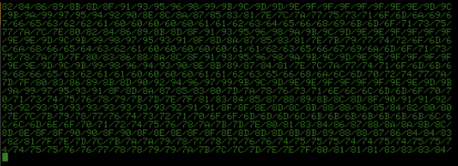
and a TEMPO of 1, I get 80 bytes output as follows (I have converted the data bytes that would be output to the DAC to HEX and terminated with a '/' character):

1704215494540.png

(The above is with the four (4) RLA instructions).

16 * 5 = 80 bytes.

If I change the RLA instructions to RLCA I get the following:

1704215641282.png

The next thing is to analyse this in more detail...

Dave
 
Dave that is awesome progress! I can't add anything but that the code I have was really the first cut and that the author did it just by looking up what seemed would do the job in the Zaks book and we debugged after I typed in the hex. If you think something isn't right and needs changing, go for it. Also I can't answer why the wave table started at (EDIT: 90 cj7hawk is right) degrees into the cycle but we were teenagers at the time 🤪
 
Last edited:
Dave that is awesome progress! I can't add anything but that the code I have was really the first cut and that the author did it just by looking up what seemed would do the job in the Zaks book and we debugged after I typed in the hex. If you think something isn't right and needs changing, go for it. Also I can't answer why the wave table started at 45 degrees into the cycle but we were teenagers at the time 🤪

The wave table appears to start at the zero crossing and go positive, which I would think is correct. The use of 20 as a center point makes sense if you think of the DAC as positive values that will be offset through a capacitor later, and with a 5v supply should equate to a central location of 2.5v when all four channels 20 are added together to make 80... Makes more sense to me than trying to use positive and negative values with zero as a crossing point.

I would probably choose the same approach if starting from scratch.
 
Which basically means (as I suspected) that the RLA (or RLCA) instructions are not required at all.

Next job today...

I have also decided against the 'serial EPROM' malarkey and just go for a 27C256 EPROM containing everything.

It is also difficult to get rid of the RAM totally. I would require 8 register pairs for 4 voices, and run out of registers.

Dave
Why 8 register pairs?
Shouldn't 4 pairs be enough?
 
Nope.

Each note will (well most likely will) have a different frequency - hence will have a different set of frequency constants (1 byte integer and 1 byte fractional) accounting for 4 register pairs.

In addition, the current 'pointer' values maintain their values in 4 register pairs.

Hence 8 register pairs will be required for 4 independent voices.

Dave
 
Wouldn't it be possible to achieve that using direct addressing with the index register? Since all the notes should play at the same time, all you need is a register pair ( integer and fraction as you call it - H.L, D.E, B.C etc ) and then this tracks where you are in the wave table.

The "Frequency" is set by adding the "Note Data" to the tracking variable. The frequency could be set and added to each pair one at a time.

eg, IX= Note Base.
Note 1 fraction IX+1
Note 1 Integer IX+2
Note 2 fraction IX+3
Note 2 Integer IX+4
etc.

Then you track the notes in DE and BC amd DE' and BC' for example.

LD A,(IX+1) OR A ADD A,E LD E,A LD A,(IX+2) ADC A,D LD D,A

etc, for each note. This gives you the fraction steps through the wavetable in the upper register...
When you've filled DE,BC,DE' and BC' you mix them.

XOR A LD H,(WAVETABLE / 256) LD L, D ADD A,(HL) LD L,B ADD A,(HL) EXX LD L,D ADD A,(HL) LD L,B ADD A,(HL) EXX

Then you have the data in A to send straight to the DAC

IX might be the number of cycles, or maybe you need two bytes for the number of cycles, but this way would give you plenty of capacity to use IX and IY as cycle counters... And you still have registers to spare....

You are correct that you need 8 pairs to do the maths, but I guess the perspective I take is half of them are constants for that particular note, means they can exist indirectly in ROM as indexed values and you don't have to move them from a table in ROM to actual register space at any time.
 
But then you still require RAM for the IX indexing, and the whole point of me trying to use registers was to get rid of the RAM.

Using registers for the 'dynamic' part of the code may make the PLAY loop shorter (in terms of T states) - so better in that respect; but it doesn't do away with the requirement for RAM itself.

And I also agree that 'unrolling' the loop would remove the requirement for a voice count register and the time associated with the DJNZ.

Incidentally, the OR A in your first code snippet should not be required (assuming this construct is designed to clear the carry flag) as the subsequent ADD instruction does not use the carry flag (ADC does of course).

Interestingly, your code is not unlike my 'scribbles' to optomise the PLAY routine - great minds think alike!

Dave
 
I have just checked the Z80 manual.

If we unroll the loop, and we use LD A,(nn+n) rather than LD A,(IX+n) we save 6T states (13 rather than 19) and now do not require the use of the IX register. Basically, let the assembler fo the work for me...

I think I will recode it like this anyhow, so thanks for the suggestion.

If I change my code first, and see if I get the same bytes output as previously, then I know I haven't made a boo boo somewhere...

I will then get rid of the four rotates (as I don't think they are required).

Dave
 
I don't think the z80 manual has an opcode NN+N.... Which code is that? I think it's likely I've misunderstood what you were saying.

An assembler can do it, but it's a fixed base - while the IX register will allow you to step through the sequence via moving IX or IY, and as I think you worked out, it can read from ROM just as well as from RAM. :) So all you need to do is step the IX register forward each time you get another note.

You will use up a few extra opcodes... But you can always run the z80 at twice the speed then - :) And you don't need decode logic if you only have a single ROM. Just use MREQ as your Output Enable and keep CS low. It's a shame you can't get rid of the oscillator circuitry or you could reduce it to just 3 chips ( you can use IORQ to latch a single 8 bit register )

You can always recalculate the note table in Excel and rebuild the table very quickly. Or write a simple program to generate that code. Which makes me wonder if any assemblers count the cycle time between two points.
 
The assembler would add together nn+n and convert that into a single constant.

Basically, unrolling the code (so it isn't in a DJNZ loop) means that we don't need to use (IX+n) to index a byte (requiring 19T) but (V1F) (a symbolic reference to Voice 1 Fraction) taking 13T.

I have done a few sample code fragments and come up with 140T (using 16 bit loads and arithmetic) rather than 176T (using 8 bit loads and arithmetic).

I will post the code when I can wrangle the iMac off the wife and try it out - so you can see something concrete...

Dave
 
Here is the printout from the asm80.com website for my latest source (see attached Zip file):

1704315778357.png

Various bits of debug code are in there at the moment.

I have unrolled all of the loops - so the code should be faster than if the loops were in there, but at the expense of code size (which is not so great as it stands actually).

I have resisted the temptation to convert things to use register pairs for the following reasons (after spending a lot of time with a pencil and paper and throwing various designs away):

1. My brilliant idea [sic] fell onto stony ground because a key instruction I required for my code didn't actually exist within the Z80! That doesn't stop you from writing it on a piece of paper, but it causes consternation when you try to look up how many T states a none existent instruction takes!

2. The design started to get quite horrendous when I looked at the code that would have to exist around the fast parts. For example, the TEMPO and DURATION is required to be retained outside of the loop iteration.

However, now that I have unrolled the code, I have simplified some of the internal structure (for example IX is now a complete constant throughout the program) so I may be able to restructure a bit more to accommodate the desired register pairs for the variable registers of the four voices.

What is the phrase, slowly slowly catchy monkey...

Anyhow, you should be able to use asm80.com to import the .z80 and .emu file and it should assemble (compile [sic]) and emulate for you.

If you spot any typographical errors please let me know and I will fix them, or have any further constructive suggestions...

Enjoy...

Dave
 

Attachments

  • MUSIC 20240103.zip
    30.6 KB · Views: 4
I have made a slight tweak to the code this morning in readiness for having a go at using register pairs to hold the relevant data for the four voices.

I have moved DURATION and TEMPO into IYH and IYL using the documented undocumented Z80 instructions.

However, I have also added a 'Z80 compatibility mode' conditional assembly option so that RAM is used instead. Obviously, the RAM solution will be slower (in terms of T states).

I have also added some symbols for DEBUG and TEST to make the source code easier to (well) debug and test (as it says on the tin)...

I think I now have the PLAY subroutine sorted out for register pairs but I am still fighting with the MUSIC subroutine. I may end up having to save BC onto the stack (in MUSIC) and recover it before calling PLAY. The register pairs DE (Voice 1), BC (Voice 2), DE' (Voice 3) and BC' (Voice 4) have to remain untouched throughout MUSIC. Both HL is used (as the SCORE pointer) and BC (as the index into the frequency table). So I have to save and reload BC I think to/from the stack.

Interesting 'almost' bug. When I switch the register sets (using EXX), HL also is switched (this is used to index the wavetable). As a result, I am having to load up H first and use this with D and B then reload the shadow H again after the EXX before I can use it again with D' and B'.

Dave
 
Last edited:
Just been doing a bit of prototyping on paper this afternoon...

For the original code loop for one voice (updating the variable and computing the DAC value from the integer part and looking that up in the wave table) I get 153T states.

Cjhawk's code (from post #29) for the equivalent gives me 62T. This code uses 8 bit loads and maths, and the index register IX).

If my 16-bit load and maths works out in practice (using the HL register pair and direct addressing instead of IX) I should be able to reduce this to 43T.

My pseudo code is:

LD HL,(V1FC)
ADD HL,DE ; DE pair holds V1V.
EX DE,HL ; Put the answer back in DE.

I can't do the same trick for the BC pair, so I have to replace the EX DE,HL with LD B,H and LD C,L. This takes marginally longer, so I have used the worst case for my timing analysis.

In both cases (cjhawk's and mine) the computation for the DAC value takes 8T (as opposed to 39T for the original).

I will have a go at my 16-bit attempt later.

Dave
 
Ah ha, I have some success with my register variant of the code...

I broke the asm80 assembler though - so I have created a MUSIC2.z80 file.

I am not 100% happy with my code yet, so I will play with it a bit more tomorrow. It is, however, generating the same DAC output as my last attempt...

I messed my maths up by a few T states in my comparison. I am just commenting all of my current code with the T states and then will run the calculations again.

I will also have to create a spreadsheet to recreate the frequency table for the new timing values.

Dave
 
The spreadsheet to generate the frequency table is now done.

It very closely agrees with the 6502 numbers + or - 1 in the fraction.

I now have to do the T-cycle count for my Z80 program, and persuade the spreadsheet to generate the data table in the format I want it in so I can copy and paste it into the assembler program.

Dave
 
Right, the latest offering for your enjoyment or amusement...

The attached ZIP file contains the Excel spreadsheet to calculate the frequency table given the clock frequency (4.0 MHz) and the number of T states in the PLAY subroutine. It also contains the latest MUSIC2.z80 source code.

I am quite proud of this, as I have been able to reduce this to 248 T-states giving a sample frequency of 16,129 Hz (or a period of 62 microseconds). This is virtually double that of the sample frequency of the 6502 variant (albeit with a clock that is four times faster).

I have used a single note as my test case (C2 = 65.405 Hz).

Here is the diagnostic output:

1704471408580.png

I see that the DAC value starts off at 0x80 and goes up to a maximum of 0x9F and a minimum of 0x60. This is +0x1F and -0x20 - consistent with a single voice ranging from 0x00 to 0x3F.

I have counted the number of output bytes (samples) from the first 0x80 to the second 0x80 (half cycle). I count 123 samples. Therefore a full wave should be taking twice this (or 246 samples).

Multiplying the numbers together gives 246 [samples] * 62 [us/sample] [and converted to seconds] = 0.015 s.

The reciprocal of this gives 65.565 Hz - pretty close to C2 at 65.405 Hz.

The other way of working it out (as a check) is to divide the sample rate (16,129 [Hz]) by the number of samples (246) giving 65.565 Hz also.

Of course, this does not include the time taken outside of PLAY (i.e. within MUSIC itself); but that is another story.

There is still some tidying up of the code and comments to do - and (of course) adding the score for a real tune (or tunes)...

You also need the .emu file from my previous ZIP file to run the assembler file under asm80.com.

I am now looking at the hardware to build one...

Let me have any constructive feedback...

Dave
 

Attachments

  • MUSIC2 20240105.zip
    31.4 KB · Views: 3
Last edited:
Back
Top