• Please review our updated Terms and Rules here

Getting a SuperPET online

Okay, I tested the devices (not connected to each other):

WiModem232:
Across pins 2 to 7 = 5.58VDC
Across pins 3 to 7 = 0VDC

SuperPET:
Across pins 2 to 7 = 10.45VDC
Across pins 3 to 7 = -0.07VDC

Do the SuperPET voltages seem off?
 
>>> Okay, I tested the devices (not connected to each other):

That is exactly correct.

>>> Do the SuperPET voltages seem off?

Why do you say that?

I think the opposite. The SuperPET voltages seem correct for RS232 levels.

It is the WiModem232 voltage that looks low to me.

What I deduce from this test is that pin 2 of BOTH units are the 'transmit' signals, so we have to wire pin 2 of the SuperPET to pin 3 of the WiModem232 and pin 3 of the SuperPET to pin 2 of the WiModem232 for correct operation.

At the WiModem232 end, I would also connect pin 4 to pin 5, and pin 6 to pin 8 to pin 20 (hardware handshakes looped back).

Don't forget pin 7 to pin 7 (0V).

Does this make sense?

Dave
 
10.45V just seemed like an odd number to me - like something that would fry the WiModem. But I see online that the RS-232 specs say voltage can be between 5V and 15V....and the SuperPET serial port manual states it can be from +3V to +30V for logical 0s and -3V to -30V for logical 1s.

Interesting that both seem to be transmitting on pin 2, as from what I understood, DCE (SuperPET) to DTE (Wimodem) communication required a "straight through" connection. Seems like something is not conforming to spec, in that regard. But obviously since I'm still learning about RS-232 communications I could easily be mistaken.

Everything makes sense. I will build the cable you describe.
 
This is always the fun and games with RS232...

The RS232 electrical specification states nice, high +/- Voltages.

There is a 'much reduced RS232' specification that reduces the voltages.

There are then 'TTL signals' that are also described as 'RS232'.

Interconnection of the latter with the former just lets out the black magic smoke from the latter...

This is where you need to obtain and read the specifications carefully.

>>> Both are transmitting on pin 2.

Exactly, that is what I wanted to find out...

I have a very nice RS232 tester that I made myself (in the old days this is). Everyone that saw it wanted one, so I got a trainee to make up 10 units. They all disappeared within minutes...

It had a 10x10 matrix plug board, two sets of 10 LED indicators, and a male/female 25 way pass through on the sides of the matrix plug board.

You plugged one side of the cable into one side of my tester and the other side of the cable at 90 degrees to the first.

From the state of the LEDs you could tell at a glance which pins were driving outputs - the LEDs were illuminated.

By plugging pins into the matrix plug board you could now correctly connects tx to rx and either jumper out the hardware handshake signals or connect them appropriately.

You could also purchase diode pins in two different configurations of the diode arrangement (different coloured pins). You could split and join using this type of arrangement (but this was a very rare use).

Dave
 
Just a question while making this cable: is a ribbon cable acceptable for 3 ft run of Serial cable? Or does it have to be shielded cable?
 
Okay, I'm here to report some surprising progress.

First of all, I constructed the "cross-over" (pins 2 and 3 cross-connected) serial cable as Daver2 instructed above. This cable connects pins one to one and seven to seven straight-through to the modem, as well. It also Loops back pins 6, 8 and 20 on both the modem and the computer side. It Bridges pins 4 to 5 on the computer side, and pins 4 to 5 on the modem side.

Unfortunately, it did not work. No change. Tested it with both the Wimodem 232 and a US Robotics "real" modem. No response from either. No response to AT commands.

I then resoldered the cable so it was a straight through cable with pin 2 connected to pin 2 between the computer and modem, and pin 3 connected to pin 3. This resulted in a Echo of characters typed. Same behavior using both the Wimodem and the US robotics modem. But still NO response to AT commands.

20240718_225624.jpg

I then reverted to using the original commercially-made straight-through rs232 cable I had been trying earlier. This is also didn't result in response to AT commands from the Wimodem, as had been the case earlier. No character echo either.

I then hooked up the real US ROBOTICS modem to this cable. Same result. No Echo and no response to AT commands, seemingly.

That was...until I issued AT&C0 (get/set DCD operating mode). Then suddenly I received an on-screen response stating "OKAY " from the US Robotics modem. Also any characters I typed were being echoed back. This was remedied by ATE1 which stopped the Echo.

I was now fully connected to the US robotics modem and able to get status reports from the modem:

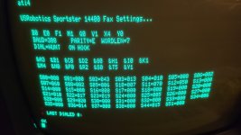
20240718_222721.jpg

I was even able to dial up a BBS using my POTS landline:

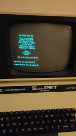
20240718_232922.jpg

I thought I had finally solved the problem of connecting a modem to my SuperPET. So I shut everything down and connected the Wimodem232 to the cable. Unfortunately, issuing the same AT&C0 command from the terminal did not result in success. So the Wimodem232 still does not work.

I'm stumped right now as to why the US Robotics modem is fully functional with the SuperPet, but the Wimodem 232 is not. However I feel we are getting closer to finding out.

I wonder if the TTL voltages issued by the Wimodem232 via its rs232 port are too low to be registered by the SuperPet as valid 1's and 0's.

I also don't actually understand what AT&C0 does. I don't know what DCD is.
 
Last edited:
Did you do the voltage check between pins 2-7 and 3-7 on the USR modem? If not, they may be reversed compared to the WiModem232...

You are running way ahead... I was going to suggest a more leisurely pace - but you are getting somewhere...

I would more think the problem is associated (still) with the hardware handshaking...

Even though we have 'shorted out' the hardware handshaking signals at both ends - they still require a source of voltage (on a source pin) to drive the associated inputs. On some equipment, this is provided by a pull-up resistor. On the SuperPET (and the USR modem) this is not necessarily true - and we may have to configure one (or both) ends to ensure that the hardware handshake signals are either ignored (on reception) or active (on transmission).

This is (effectively) what you did by entering the AT&C0 command. You set DCD (Data Carrier Detect) to permanently ON. This signal is used to indicate that the modem can 'see' a carrier signal on the telephone line. It signals back to the 'terminal' that it is online to something at the other end. The default (for the USR Modem) will be deactivated - so the DCD signal is not providing the correct loopback voltage for the pins we have wired it back to. Sending the command AT&C0 activates DCD permanently. We could also have sent the commands to switch off checking the signals coming back to the USR Modem.

That should explain what DCD is...

You didn't do the previous check that that I asked for to make sure that the echo on the SuperPET was due to the pin 2-3 loopback. I see you permanently installed a link between pins 2 and 3 - and I asked for the pins to be both connected and disconnected - just to make sure that the echo is as a result of the loopback link.

Since you have success with the USR modem, I would continue with that for the time being.

Dave
 
What is the configuration that works from a complete power up?

Is it a commercial cable, plus the USR Modem, plus the AT&C0 command, plus the ATE1 command?

If this is correct, we can compare the USR Modem signals with the WiModem232 signals.

The first thing is (as usual) to check the voltages between pins 2-7 and 3-7 of the USR Modem...

If these are reversed, then all you do by swapping the modems is introducing a new problem that you didn't have before!

Incidentally, I would expect the SuperPETs MC1489 RS232 receivers to work with the WiModem232 low voltage levels. I do not see any specific components around this IC to indicate that it should not work.

Dave
 
The Amiga 1200 RS232 connector has TX on pin 2 (via a 1488 RS232 driver) and RX on pin 3 (via a 1489 RS232 receiver).

As a result, the WiModem232 SHOULD have RX on pin 2 and TX on pin 3 (i.e. the voltages you measured in post #21 does not make sense).

Note that the RS232 1488/1489 driver/receiver chips are the SAME on the Amiga 1200 and the SuperPET.

As a result, the WiModem232 SHOULD drive the SuperPET OK.

Note that the default baud rate for the WiModem232 s 300 BAUD. You are setting the SuperPET to the same speed aren't you? Have you tried the "ATI" command on its own?

According to the manual, the AT&C0 command is supported. However, it will only work correctly if the SuperPET and the WiModem232 can correctly communicate with each other!

Manual: https://www.cbmstuff.com/downloads/wimodem/wimodem232_manual.pdf

Dave
 
Last edited:
Thanks Daver2 for all your support to this point. It’s much appreciated.

First of all – I need to correct an omission in my last post. Using the following configuration:
SuperPET RS232 ----> Commercial Straight-Thru 25-pin serial cable ----> USR modem
Upon immediate startup (and loading the microEDITor and starting TALK), I was able to initiate one-way communication from the SuperPET to the USRobotics modem. I.e. when issuing at an ATA (answer command), I was able to get the modem to pick up the line and issue a carrier tone. However, I was doing so blindly...I could not see any echo or text response from the modem on the SuperPET’s screen. I suspect that when I issued an ATI command, the USR modem did receive it (I could see the RD and SD lights on the modem flickering), but no text appeared on screen.

It was not until I issued the AT&C0 command that text from the USR modem would appear on-screen. Also, upon doing that, any text I typed was suddenly echoed back (i.e. AATTII instead of ATI) and I was able to remedy that by issuing at ATE0 command.

I’ll try and answer your questions carefully, below:

>>Did you do the voltage check between pins 2-7 and 3-7 on the USR modem? If not, they may be reversed compared to the WiModem232...

With my multimeter COM (black) lead connected to PIN 7:
  • Between pins 2 and 7: 0VDC
  • Between pins 3 and 7: -12.71VDC

>> You didn't do the previous check that that I asked for to make sure
>> that the echo on the SuperPET was due to the pin 2-3 loopback. I see you
>> permanently installed a link between pins 2 and 3 - and I asked for the
>> pins to be both connected and disconnected - just to make sure that the echo
>> is as a result of the loopback link.


You’re right. I neglected to do this. Sorry if this has made things more difficult.

>> What is the configuration that works from a complete power up?

The configuration described at the top of this message is the one that works from complete power up.

>> Is it a commercial cable, plus the USR Modem, plus the AT&C0 command,
>> plus the ATE1 command?


Yes. Please note that I can still issue commands to the modem prior to issuance of the AT&C0 command, but I am doing so blindly. The SuperPET does not receive text from the modem until AT&C0 is issued.

>> If this is correct, we can compare the USR Modem signals with the WiModem232 signals.

New test results of voltages on the WiModem 232 with my multimeter COM (black) lead connected to PIN 7:
  • Between pins 2 to 7: 0VDC
  • Between pins 3 to 7: -5.57VDC
(I realise this is different to my results I had posted in post 21. This is my error.)

>> Note that the default baud rate for the WiModem232 s 300 BAUD.
>> You are setting the SuperPET to the same speed aren't you?
>> Have you tried the "ATI" command on its own?


Yes, the SuperPET is set to 300 baud (0300) in the SuperPET’s ROM Setup configuration screen.
Yes, with the WiModem connected to the SuperPET at 300 baud, using both the commercial 25-pin straight-through cable and the home made cable, I have issued the “ATI” command. There is no response from the WiModem.
I have also tried to issue a few commands to the WiModem that would change the status LED on it (so I could determine if anything was getting through) such at AT*LED0 and AT*WPS. There was no change in the status light on the WiModem.
I have also tried issuing an AT*D1 command to the WiModem (DCD polarity invert) with no success.
And lastly, I have checked to see if the WiModem is in QUIET mode (ATQ1/0). No success.
 
That makes more sense now (regarding pins 2 and 3).

It looks like pin 3 is transmit (from both the WiModem232 and the USR Modem). So this makes sense for the straight through cable.

I was expecting a negative voltage - but made the assumption you may have had the mutimeter leads around the other way to get a reading on your multimeter. Perhaps that was an assumption on my part that I should have checked with you?

As expected, the USR Modem RS232 signal levels are higher than than the WiModem232 voltages.

I suppose the next sensible question would be: do you have a V1 or V2 WiModem232 and how are your links actually configured (assuming you have one with links).

Let me digest the reset of your post...

Dave
 
You should be able to configure your USR Modem correctly (AT&C0, ATE1, etc.) and then issue a command to write the current configuration to (say) user profile 0.

You can then command the USR Modem to power-up with user profile 0. You may have to send the Modem a command or there may be a switch configuration on you modem.

If you can work out the command sequence for your specific Modem, then everything should work OK from a power up WITHOUT having to issue commands from the SuperPET...

Dave
 
I was expecting a negative voltage - but made the assumption you may have had the mutimeter leads around the other way to get a reading on your multimeter. Perhaps that was an assumption on my part that I should have checked with you?

I suppose the next sensible question would be: do you have a V1 or V2 WiModem232 and how are your links actually configured (assuming you have one with links).

Dave

Yes, you are right. I had the probes reversed during my initial testing (Post 21). That was me not understanding that PIN7 was signal ground.

My WiModem is silk-screened with V1.1 on the circuit board.

I would also like to try a firmware update, in case that fixes the issue --- but not being able to connect to it in the first place makes that difficult. I would have to pull out an old laptop and make a DB9 to DB25 serial cable.
 
Actually, some of them might be bridged under the shellac coating, but it would be as it came from the factory (as in the photo in post 31.
 
I was able to hook the Wimodem232 up to an old laptop with a physical serial port using a 25 pin to 9 pin serial cable.

I was able to access the Wimodem232 through this setup and get it online. I was also able to update the firmware and the modem to the latest version.

Even with the firmware upgrade, the Wimodem still doesn't work with the SuperPet.

So...what I can conclude so far:

- the Wimodem232 is functioning (verified when connected to laptop using a 9 pin to 25 pin cable)
- the SuperPet serial port is functioning (verified connected to an external US ROBOTICS modem using a 25 pin to 25 pin straight through cable)
- Wimodem connected to SuperPet via same cable does not work (tested using the same 25pin to 25 pin cable)

The only thing I can think of that would be causing the incompatibility is that the wimodem is unable detect the range of voltages that the Superpet's serial port provides. Essentially the Superpet's signals are out of range for the Wimodem, even though those signals coform with RS232 specifications on paper.

Or it could be that the Wimodem232 is putting out signal voltages that are too meagre/narrow to be read be the Superpet's serial port (TTL VOLTAGES). However, Daver2 said above that the Superpet's ACIA chip is the same as that used in the Amiga 1200, a computer with which the Wimodem has been confirmed to work.

I've run out of ideas.
 
Howdy! So, which version of the WiModem232 do you have (V1, V2, or PRO)? I don't see any pictures of it in this thread.

Since you have verified that the WiModem232 works with something else, and the SuperPET works with a real modem (which required changes to the DCD in order to see anything), then I would say your cable is "probably" correct. Keep in mind that the WiModem232 emulates the Hayes protocol and interface specification exactly. You will need to have ALL of the lines passed through using a MODEM cable, not a NULL-MODEM cable (as you found out). Just make sure you are not using a DB25->DB25 or DB25-DB9 cable that is missing some lines. I am not sure what the SuperPET requires, but since the real modem works I would expect the cable to be correct.
The WiModem232 supports +/- 15v (+/-25v peak) standard RS232 signal levels. Lines that "float" or have no current load could read a variety of voltages, so you really can't go by voltages for operation. If you have a DB25->DB25 RS-232 tester (little box that goes between the computer and the modem) that will tell you everything about what is going on. My guess is that the computer doesn't like some state that the WiModem232 is in by default, which I find a bit odd because it is the defacto standard. I have never had anyone so far (out of thousands of these in use) not be able to connect to any type of computer system. Here is the magic device I use to look at the RS232 levels:


You can use any of the various devices. This one is handy because you can turn on/off each of the lines. When you are sending data to the WiModem232 the LED blinks with each transmission of bits. Same for receiving. This takes the mystery of what is going on.

Does your WiModem232 have a display? If so, it will show info when you press the RETURN key after entering a command. It will also show you the current baud rate. By default, it is set for 300 baud. Make sure the terminal really matches this baud rate. If you enter data, like ATI and press RETURN you should see "ATI" on the WiModem232's display. If you don't see that then there is no communication TO the WiModem232, which might be caused by the terminal software not thinking that something is connected (like your AT&C0 discovery with the real modem). Let me know what type of WiModem232 you have, and if it has a display.

I will look into the SuperPET. It sounds like it uses the old school 1488/1489 RS232 transmitter/receiver pair like the Amiga. I will have a look at the schematic of the SuperPET.

Have you tried another terminal program?
 
Back
Top