If your CPU isn't running right, it's probably never getting to the instruction that polls the keyboard port and triggers the wait state generator.
I am sorry to keep beating the proverbial dead horse, but you have verified that the CPU is resetting correctly at power-up, right? It's unclear to me from skimming back over the previous posts.
That reset signal not only resets the CPU, but it resets the latch that generates the NMI at the start of the vertical blanking interval. If that's never getting reset, that might also explain why you are getting a barrage of NMIs instead of just one whenever the CPU writes to video RAM. Grab that schematic earlier in the thread and check both the inverted and non-inverted reset signals. Maybe if there's a bad inverter somewhere some of the stuff is getting reset and some of it is staying in an undefined state.
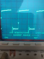
You should see it pulse for a moment when you power up the computer, and when you do rightshift-reset from the keyboard. You may need to put your scope in single seq mode and set the trigger slope (rising or falling) to the right thing to catch it. It will be very brief, maybe too quick to see on a digital scope without grabbing a single seq.
I hope I'm not leading you on a wild goose chase. My apologies in advance if so!