• Please review our updated Terms and Rules here

Homebrew TVT I picked up

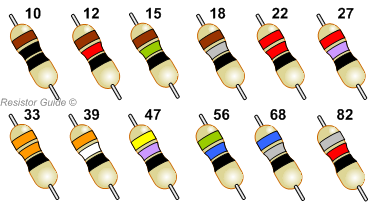
Well, like everything else, colors fade with time, so good lighting and an eye toward comparison with other similar resistors helps.

As an aid, there are standard resistor values, so if you're unsure, these can be a guide, so 290 is not a standard value, but 390 is.

That's not to say that non-standard resistor values can't be encountered, but the odds are with the standard values.
 
Ok.. did I do the wrong thing? I removed the 390ohm resistors from the cursor board, and replaced them with 1k. This caused the entire TVT to essentially freeze up - I can see the characters onscreen but there is a high frequency waviness to them. The keyboard will not function (all the pins stay low no matter what you type), and the UART loses its clock completely. If I remove the cursor board, everything is back.

Should I have put the 1K resistors on the EPROM on the UART board?
 
We are not sure what you are doing. What board are you referring to as the cursor board?
There are several place on the boards where there are some resistors. The resistors I have been talking about are only on the outputs of the EPROMs.
If you increased the resistance on one EPROM, and had an issue, replacing them on some other EPROM will not make it better.
Please start using the scope rather than the probe.
Dwight
 
If you've seen the pictures, the EPROM I'm referring to is marked '3' and is installed on the board furthest to the right. I call it the cursor board because when it is removed the cursor is gone. Because that was the one that my probe was causing improvements with, I thought that was the one we needed to raise resistance on the output pins of.
 
We really need to understand what the three EPROMs do. You need to use a scope instead of a logic probe.
I suspect that the board you call the cursor board has the keyboard translator EPROM. That makes one wonder why it also effects the cursor.
I'd thought one of the other two EPROMs were more likely this function but I seem to be wrong. Why do we need the EPROMs in the first place, needs to be answered.
For now, lets not make any more changes to the original design. Put 390 ohm resistors back in place for now. We need to see if we can make some sense of what the EPROMs are doing. It will be more useful to control which characters we are using. Please put it back in the loop back. The key board seems to be creating the correct characters.
If you hold the key down, is the data being held constant from the keyboard?
I want to go back to something we followed earlier but now I'm not sure of. When you followed the lines from the keyboard, did these wires go to the EPROM with the #3 label?
Also, earlier I'd asked for you to follow the RAMs address line through one of the muxes to the two counters. We still need to know which counters are used for RAM entry and which are used for video scanning. Please do this as we can do with a lot of experiments that can't be done without knowing what we are looking at. Also, when you are not entering a key, what state is the select line of the RAMs address muxes?
Dwight
 
Although, this may have used the basic ideas from Lancasters TVT, it doesn't match either the book or RADIO-ELECTRONICS article. This has 64 characters, wide, while Lancaster was using 32 characters. The RAM memory was quite different as well. The article use a RAM chip that had a single data bus for read and write. The book is about the most useful but it has differences from there as well.
Dwight
 
The TVT II used 6x2102s for 2 pages of 32 characters wide. Several (myself included) simply modified the board slightly to get 1 page of 64 characters wide.

The 6 2102s were sufficient because only uppercase was supported.
 
Standard 5% resistors would have the values:
10 Brown Black
11 Brown Brown
12 Brown Red
13 Brown Orange
15 Brown Green
16 Brown Blue
18 Brown Grey
20 Red Black
22 Red Red
24 Red Yellow
27 Red Violet
30 Orange Black
33 Orange Orange
36 Orange Blue
39 Orange White
47 Yellow Violet
51 Green Brown
56 Green Blue
62 Blue Red
68 Blue Gray
75 Violet Green
82 Grey Red
91 White Brown
Then some multiplier of 10^n
Note that they are in about 10% steps. Some times it is hard to distinguish Brown/Violet, Brown/Orange or Red/Orange.
Dwight
 
Last edited:
Believe that I posted something back in #181 to the effect.

The most common first two bands are these (E12):

resistor_standard_values_E12.png
 
I'm game for using this Rigol if someone wants to give me a primer. I have been (slowly) working through the manual, some videos, etc. I find it a bit over my head. This stuff is sort of math related and math was always my weakest subject; my teachers thought I had some kind of learning disability because no matter how simply we broke it down, no matter how many after class tutorials I attended, I just couldn't get it. Did very well in all other subjects but math nearly scuttled my graduation from high school. So when I'm trying to understand square waves, sin waves, etc... it's almost panic inducing. :) But I am working through it. I just don't want to embarass myself misreading instructions or information I'm getting to further confuse the situation. I've been experimenting with this thing a bit on my TVT, which shows some of the patterns you look for under normal operation and goes through troubleshooting steps in granular detail. It's sort of giving me a goodish primer. Lancaster really did know how to break things down for simpletons like me.

But yeah, I will reverse what I did and then continue documenting the circuit (I've been trying to develop a whole picture rather than one part, but I can focus on what Dwight suggested for now). Is there any purpose made software one could use for reverse engineering a circuit? I'm finding my pen on paper method gets messier and messier as I go.

I feel like the first EPROM, which is on a little perfboard by itself, is the translator. The keyboard wires directly into it, and you can see the address and data out pins changing as you type. The thing that is weird about it vs my TVT, is on my TVT if you type something, it only holds the bit pattern generated until you release the key. On this one, it stays until the next key is pressed.

Anyway, I'm pretty confident that's what that EPROM does. I'm also fairly confident that the board with the EPROM I've been messing with is the cursor control board, and the one beneath it is the tape encoding/decoding board. I've no idea what the EPROM by the UART would be for. My guess is with those custom ROMs he had on his 6800, he might have had it sending stuff that had to be intercepted and translated differently. I was actually looking at the circuit comparing it to my GT-6144 - I thought if he went to the trouble of building the AC-30's tape functions into this thing, maybe he also built graphics or something weird like that into it as well.

Another possibility, maybe one of the EPROMs helps with the tape encoding/decoding.
 
Last edited:
Does the Rigol have an "AUTO" button? Start there--hook a probe on something and hit AUTO and see what gets displayed.

But you should probably start by adjusting the compensation on your probes. The user manual tells you how to do that.
 
I'm looking at the online manual for the 1000 series. For the most part, I don't see anything with the Math button that will be useful in debugging your board. Pay more attention to the Vertical, Horizontal and Triggers. Those will be the most important things to deal with. The Math operations are post processing of the signals you've sampled. There are a number of really nice feature in the Math stuff but nothing you might want to use on your board.
Dwight
 
Okay. Let me work on undoing my mistake here and then I'll hook up and we can see where this goes.
 
First, look at the character generator chip( https://www.atariarchives.org/cgp/Ch02_Sec04.php ). You can see the bits it expects to send are set up as rows and columns. It has outputs that correspond to the rows to send as the dots. Note that the columns are addressed backward from D6 to D0. This is simple to handle, D6 will be the first dot to send to the video and D0 will be the last. These need to be serialized to the video. This would be done by the dot clock ( most likely the clock from the crystal or divided ). It could be serialized 2 ways. One would be to have a shift register that can be parallel loaded into a shift register but I don't see any specific shift chip for that. It could be done another way, using a 6 to 1 mux and a counter. I don't see anything that looks like that either. A shift register can be made with individual flops and some gates. There are some 7474s or 7473s that could be used for that purpose. Since these need to run with a high speed clock, you might look at these with your scope.
There are a number of counter chips. There would be a video character counter. This needs to run at the next lower speed than the dot counter. I can see some 7485 chips. Those are comparator chips. The input character counter would be compared with the video character counter to create the cursor on the last row of a video character. I suspect one each of the input channels of these, 7485, chips are used to determine the cursor position. You might trace these inputs to see where they go. It is a little complicated as to how the video counter works. For each character, it needs to count across the row for each character and then increment the character count for each of 64 characters. It must then increment the row counter for the next row of dots. It must stay on one character until it completes a row of dots from the character ROM. It must also reset the LSBs of the video character counter such that it repeats the video character LSBs counter for each of the 64 characters, the number of rows for the character ROM dot rows. When it has finished the last row of dot bits, it must then increment the MSBs of the video character counter. To start the next row of characters. 64 character are counted with 6 LSB bits. The rows of characters are counted with 4 MSB bits. Since these counter run continuously because they keep the display running.
The other side of the 7485s would then only change when one type a character and then only once per character. By scoping out the 7485s, we should be able to determine which chips are for what.
The chip(s) connected to the output of the character ROM ( 6571A ) should either go to a shift register ( possible multiple flops ) or to a mux ( 74157 or gates ).
Once we know which is the input character counter, we can use the trigger on the scope to see what each of the data bit is coming from the RAM. I suspect the RAM bits go to one of the EPROMs near the UART. That would leave one EPROM left to figure out.
Once you have those pieces identified, we can do some experiments to figure a lot of things out and see why things are working so poorly.
Find and mark what you think are the video character counter chips and the input character counter chips.
Dwight
 
The chargen is connected to a 74165. There are also two 7495s on the same board that seem to interact with it somehow. I'm trying to sort through the tangle of wires but it's tricky. I'm wondering if it'd be easier to use the other logic probe I have with the pulse function to suss these out.. if I understand that one correctly, you can hook it up to a given point on the board, and then send a pulse around that you can then find with the probe?
 
Your really better of using your scope. You can't see if a signal is cyclic of not symmetrical. Clocks will be symmetrical data not. Oops I just edited. it was a 74165. That is the right one to serialize the output of the character generator.
Dwight
 
Last edited:
Dwight, I didn't know that you had a Rigol 1000Z-series scope.

No, I was looking at the manual online.
It has a bunch of math and logical operations. On the math side, you can do things like FFT or exponential. Logically, you can to things like ANDing, Oring or XORing saved patterns. These would be useful for some digital operations but generally of little use during normal debug.
As an additional note the best doc for 6571A is:
https://bytecollector.com/archive/mark_8/My_Mark-8_Info/DigitalGroupPacket/M6570.pdf
Dwight
 
I have been working on documenting the circuit. It is tedious work, and a bit mind bending because of how hard it is to distinguish the wires from one another.

In terms of troubleshooting I've decided to order a replacement card socket before I go further. As you can see by this picture, the socket took a heavy blow while this unit was in transit, as did the keyboard, which broke the PCB in a few places. The socket was literally broken into two pieces. Because the two sides of the socket were held by screws, I realigned the sides, pulled out broken plastic and make sure the 'teeth' were lined up. From a visual and continuity perspective they seemed to be, but maybe not. That cordless drill battery you see in the photo causes everything to work just as well as if I'm probing with the logic probe - I realized the amount of force I was using with the probe was bending the board down, so I tried simply putting weight on it, and.. it works.

I'm thinking either the broken socket or possibly a cold solder joint somewhere on the card might be giving me issues. Anyway, I'll do due diligence and replace the socket before going further on diagnosis.
 
Back
Top