• Please review our updated Terms and Rules here

Honeywell 200 resurrection

I confess very little experience with Honeywell iron, other than their old instrumentation gear (controllers, chart recorders, pneumatics, etc.). I did visit a friend who moved to Phoenix shortly after Honeywell bought the old GE plant to give me a tour of that operation. At the time, the engineers were working with direct water cooling of packages. When I saw the system, it was in an enclosure about the size of a tool shed with open racks inside with lots of small hoses going between the assemblies. I suspect this was the prototype for the 66/85--I don't know if it was ever shipped. It was a lot more interesting wandering around the plant floor and noticing all sorts of GE hardware stashed away in various corners. The engineers did have an interesting console, however, with multiple CRTs and neon bar-graph displays.

I do recall reading in the trade rags sometime around then that Honeywell had re-done one of its models in standard ECL rather than the CML they'd previously used. I read that the rework didn't gain much, if anything.

Thus beginneth and endeth my tale of experiences with Honeywell computers... :)
 
It amused me that Honeywell's operating system was called GCOS (General Computer Operating System presumably) but if one looked at the code for it there were still places where its original name GECOS hadn't been changed to GCOS.
 
Dr William L Gordon, chief designer of the H200, may well have been involved in that as before working for Honeywell he worked at the NSA with top security clearance.
 
Back in the 1970s, I worked with several GSA types who were involved in WWMCCS programming. A fair number of my unit at CDC were involved in NSRDC projects. Then there were the ROVER people who didn't talk to anyone and pretty much lived in a screen room. CDC was full of interesting projects back then.
 
If you keep looking through the GCOS source you will also find references to WWMCS code too.
Do you have access to any GCOS source? We've been trying to locate any kind of GCOS version to test the DPS 8/M simulator with. We have Multics running on it and Multics has a partial simulation of GCOS batch and TSS from the release 4JS3 of GCOS.
 
Do you have access to any GCOS source?

Sorry no source. In the early 80s we ran version 3I in production and were testing version 4JS2. We built the whole OS from source just to insure that we had everything. I wish I kept a source tape, but at the time it seemed pointless.
 
So now that I am resigned to making my own control panel for my H200 replica I have made a very modest start on that, most of my time having been in demand elsewhere. Fortunately my ex Honeywell field engineer friend, having recovered from his seriously shattered leg injury, got into his loft and found there an original control panel fascia, so he created from this a full size template showing where all the holes for the buttons are. This ensures that my panel will be an accurate replica regarding the exact positions of the buttons.
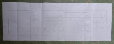
Panel template.JPG

However, this fascia was clearly from a later machine in the H200 series as the earliest design H200, such as the one in the previously mentioned film Billion Dollar Brain had a slightly different layout. This template corresponds to the H120 panel in the Rhode Island Computer Museum but the same layout was used for all later machines in the H200 series such as the 1200 and 2200. My own website https://honeypi.org.uk/ shows a CGI representation the original H200 panel which I intend to build. One evident difference in it is the use of a single toggling Address Mode button to switch between modes 2 and 3 whereas later machines used individual buttons to switch to modes 2, 3 and 4 according to the capabilities of particular machines. However, a more subtle difference is the position of the buttons at the right of the panel. On the original machine as on my website the sense switch buttons were in line with all the other buttons on the bottom row and the Display/Enter buttons above were logically placed halfway between the rows of buttons to which they referred. In contrast on the template above and the RICM H120 panel the sense switch buttons have been moved a third of a row down and the display/enter buttons a third of a row up. This was done to provide space for a second row of sense switches on some machines and the modification then appears to have been applied on all subsequent panels including the more basic H200 according to the assembly schematic.

An extremely subtle change in the control panel was that the button originally labelled "Central Clear" as on my website was later relabelled "System Clear". This was no doubt done to make it clear (!) that the button actually affected all the peripheral devices in the system rather than the CPU as the only thing that could be regarded as "central" in this respect was the control panel itself within the system! When I was working on the H200 back in the 1960s I never understood why that button was labelled "Central Clear" and evidently nobody else did either so it was renamed, but my replica must remain faithful to that early era.

Regarding physical construction of the panel, my collection of switches came from several donors with the result that I have three different types of fitting on them in equal numbers. Some switches have side clips, some top and bottom clips and some brackets, so I can't use them all together as they are in any consistent fashion. However, they all have the same rivet holes in their casings where these assorted fittings are attached, so if I remove all the fittings entirely I can just mount all the switches with screws through the rivet holes. I have made up a small block of switches on some steel bars I had to hand in this way and there are no problems with the screws fouling the internal components of the switches, so I intend to make the whole "panel" this way although no actual panel will be needed apart from the dress fascia panel just to enclose the switches rather than support them. This approach will also allow me to assemble and wire up each row of switches individually, which will be easier than making a single large panel and mounting them all on it to be wired up there. This project is after all just a pastime for me and I always want it to be as easy as possible just to retain my sanity. The trial block of switches is shown below.
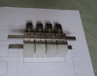
Switch bank.JPG

Unfortunately just the other day while I was machining the essential chamfers on the integral edge connectors of some new PCBs manufactured for the project the motor control electronics of my milling machine died, so I am now having to diagnose and fix the problem with that as without the milling machine I can't drill the holes in more steel bars to position the control panel switches precisely enough to match the template exactly . Ah well, one step forward two steps back again ...
 
Yes, the simulator traps on wrapping execution around at the end of memory. It also traps on illegal op codes.

I'm having trouble getting this program to run, but will follow up on PM (private message).

I noticed this remark about illegal op codes and had to think a bit about what the basic 201 CPU did with them as I don't recall seeing anything specific about that in the documentation. I vaguely recall that they were treated as halt instructions but may have to consult my friendly ex Honeywell field engineer about it. On the basic H200 which ran just one program at a time the AAR and BAR values in each halt instruction were conventionally used to return details of the program status to the operator, so I think for example 4700 meant start of program and 4777 end of program and other values were used to signal peripheral errors but any unidentified values would then imply that an illegal opcode had been interpreted as a halt by default. The basic 201 CPU was designed to be as cheap as possible and this approach to illegal opcodes would have cost virtually nothing to include. At least that is my vague recollection but of course my programs never experienced illegal opcodes so neither did I (he said smugly). It is certainly something that I will need to get right in my replica machine.

A problem with this is that there were three formats to the normal halt instruction with two, one or no addresses. In the case of one address a halt and branch operation resulted but that would have been very confusing if an illegal opcode caused a branch operation, so I guess that a non-branching halt occurred. The question then is whether the halt occurred immediately without any addresses being extracted and where the sequence register was positioned following the halt. After a genuine halt the CONTENTS display would always contain a word mark so if no word mark was present then it definitely couldn't be a genuine halt but an illegal opcode might also be followed by a word mark even if no further characters were extracted. Another possibility is that the sequence register remained pointing at the illegal opcode itself but the machine still halted. With so many possibilities I think I'll have to consult my field engineer friend unless anyone else happens to know the answer from bitter experience.

Note that the basic 201 CPU could not itself trap illegal opcodes because in that CPU trapping instructions was only provided as part of optional feature 011 which included the register CSR and internal microcode needed to make the sequence change.

Emulating these old machines looks easy initially until one gets down to the fine details. It will be quite a while before my machine can identify any opcodes at all, legal or illegal, though.
 
Great news! Just when I was knuckling down to building a control panel from scratch today I received an email from a chap near Atlanta Georgia telling me that he has one that I can have! From the pictures it looks to be in good condition as well with all the original buttons in place. We just need to sort out shipping it to the UK but Atlanta Airport is a key shipping hub so it can't be that difficult and it's even on the right side of the USA. Keep tuning in for the next exciting episode of The Honey Pi Project.

IMG_1560a.JPG
 
I am totally amazed at how quickly things have moved. Within a single day this chap has told me that he has a control panel and shipped it to me, so I now have a tracking number and estimated delivery time next week. Just to confirm this he even sent me a photo of the panel at the FedEx office awaiting packing. What a saint! Break out the bubbly!

IMG_1571.JPG
 
Wow, looks like a full panel. bit of a clean and that's that part done. Does it have the insides?

From the photos it appears that it may never have been opened and it still has the original connectors on the bottom so it was probably simply unscrewed and unplugged from the machine when that was being dismantled and then taken home by someone as a souvenir conversation piece. In a photo of the back at least two or three of the four driver PCBs can be seen through the ventilation slots so these clearly haven't all been pulled out either. If the machine was just being scrapped then it is likely that the panel was still in working order at the time as there were other far more temperamental key components in the machine that could have caused it to fail terminally if indeed it did.

IMG_1562a.JPG

IMG_1563a.JPG

The machine's most sensitive component was probably the magnetic core control memory which ran at four times the normal speed for such technology by using pairs of cores in a differential arrangement so that they didn't saturate and completely change polarisation as normally happened in core memories but instead just changed their level of magnetisation relative to each other. The working temperature of the machine had to be just right for this to work and at such high speeds the cores could easily overheat and burn out, which actually happened at the company where I worked. It is probably no coincidence that the machine was designed by Honeywell, the company that made its name by marketing thermostats! In his notes on the machine's design the chief designer wrote that the entire machine was built as cheaply and simply as possible except for the inclusion of this relatively sophisticated control memory, which gave it its enormous speed advantage for the price over the competing IBM 1401. However, it was also the machine's Achilles heel.

The truth is that I don't have the schematics for the panel, so it will take me a while to work out how to use it. If it only had the switches but not the other logic then I could just construct my own drivers and wiring without having to find out so much about the original, so either way I'll be happy with it as really I just wanted to avoid all the metal bashing needed to make one.
 
Last edited:
That does look like it has been stored well. only a little bit of rust on the top and good as new.

I cant remember reading it so sorry if your having to repeat yourself. Are you looking to have this at home or give to your local computer centre etc?
 
That does look like it has been stored well. only a little bit of rust on the top and good as new.

I cant remember reading it so sorry if your having to repeat yourself. Are you looking to have this at home or give to your local computer centre etc?

No, I won't be keeping it but then I anticipate that by the time I've finished it, if I ever do, it won't be long before I'm going where I can't take it with me. (What, you may ask, does he mean a care home?) Actually right at the outset my wife told me that it wouldn't be staying in the house, which is why I have spent several years upgrading the environment in part of our garage to install it there for the time being. However, given that many of the parts have been donated by other generous people I can only consider myself to be its custodian despite doing all the detailed work myself and I will have to think about finding it a home eventually. In fact that was the reason why I started the project, having an enormous pile of logic boards that would cost me money to dispose of as they were, so I reasoned that if I made a working computer out of them someone might be willing to take all of them off my hands for nothing, a good stock of spare parts being essential for this type of machine.

My original account written when I started out on the project was published by the auspicious Computer Conservation Society here in the UK in their house magazine Resurrection, which name echoes the name of my thread here. Of course they specialise solely in early British computers but the editor made an exception with my article as he said that it was so well written and interesting. You can read it in their magazine online HERE. As it explains it all started when my mother-in-law died ...

The important thing about this machine is that although it could be regarded as a historical reconstruction, if one applies the basic criterion of the proportion of original components incorporated into it, that isn't how I view it. The important aspect to me is the journey rather than the destination, tackling problems similar to those faced by the original designers using the components available to them but incorporating my own ideas. Wherever the machine ends up hopefully it won't be regarded as a precious relic the way that many genuine original machines are but more as something that can be played with and modified as the owners wish and if they break it then they will have the same problem that I did originally, getting rid of all the scrap electronics, but in the meantime the scrap heap won't get it for a few years more.
 
Unfortunately just the other day while I was machining the essential chamfers on the integral edge connectors of some new PCBs manufactured for the project the motor control electronics of my milling machine died, so I am now having to diagnose and fix the problem with that as without the milling machine I can't drill the holes in more steel bars to position the control panel switches precisely enough to match the template exactly . Ah well, one step forward two steps back again ...

... and now thanks to recent events one giant leap forward again! This project is certainly a roller-coaster.

The strange thing is that the death of my milling machine caused me to postpone buying the metal that I needed to make the replica control panel, but now I don't need it anyway, so did the milling machine die on purpose to delay me until that chap in Georgia contacted me? The power transistors I need to repair the milling machine arrived from the USA on precisely the same day that he contacted me and shipped out his control panel, so the timing was that critical. These are the strange kinds of coincidences typically involving such critical timing that I describe on my other website Mens Temporum (Mind of Times) as I appear to live a charmed life in many small ways like this. In fact I suspect that many of us do but don't appreciate the fact because these events and their precise timing are often so subtle that they go unnoticed or get seen simply as fortunate random coincidences.

May the force be with you.
 
Back
Top