• Please review our updated Terms and Rules here

Honeywell 200 resurrection

Oh no! The FedEx tracking system has just informed me that even though the control panel was just a few miles from Atlanta International Airport they have shipped it to Indianapolis. I recall that when I acquired a backplane from someone in Pennsylvania FedEx shipped it to Indianapolis. It appears that all their international freight goes through their hub in Indianapolis regardless of how much mileage and time that adds to the journey. Heaven help the environment.
 
Get used to it. Neither USPS nor Fedex shipping makes much sense. Recently, a locally mis-delivered package sent via USPS was shipped all the way to Portland (100 miles away) before a re-delivery was attempted. With Fedex, although the sender and recipient may be only 50 miles apart, company procedures will often send the item 200 miles or more to get to a regional processing center.
 
Do not try and apply any sort of logic to anything logistical these days - I have found it all to be somewhat random!

Dave
 
Things over there must have gone downhill since the days of the pony express. We do things on a smaller scale on our little island but the principle is much the same. There is a great liquor supplier in our town called Master of Malt which stocks an enormous variety of whisky in their warehouse right up to the rarest at the most eye-watering prices but also stocks many other difficult to get spirits. Part of the warehouse is even bonded so that stock can easily be exported without any issues over duty. I buy an assortment of spirits from them regularly and we pass their premises on our way to the supermarket every week. However, they used not to have any facility to collect orders at their premises but insisted on sending it by a delivery service. The one they chose, which laughingly called itself a "local" service, would take my order on a round trip of fifty miles over two days stopping off at their "local" depot at Gatwick International Airport on the way in order to deliver it to me just two miles up the road from the suppliers! A tortoise towing a cart could have delivered it faster so long as it didn't drink too much of the contents on the way. I complained to M of M about this so for a while they let me collect my orders from them but then decided that that was inconvenient so instead sent the orders by courier to me but waived the delivery fee. They have now provided a counter at their premises where orders can be collected so at last I can pick up my tipples on the way past without any delay. I mean, some things in life are sacred.
 
With the explosion of home delivery services you can see daft patterns emerging - but somewhat logical for 'on demand' services such as food orders from certain restaurants...

It is not uncommon for us to see the same Amazon driver arriving three times (or more) on our street to deliver parcels to separate households.

Dave
 
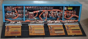
So, returning to the original subject, as I am now getting an original control panel I have to solve the earlier problem about its power supply as it apparently uses SCRs to control the lights. As neither a DC supply nor an AC one entirely fits the bill I am betting on raw full wave rectified AC being the best solution as that would turn off the SCRs every half cycle but use a very simple PSU while only feeding positive current through the control logic boards. However, with the number of lights on at any time varying so much there might be a problem with their intensity altering if the voltage sags significantly on a heavy load. Maybe a couple of headlamps on the computer would help keep the current and voltage more stable ... yes, all the lights consume around 100 watts in total so adding a couple of 50 watt headlamps would level up the consumption nicely ... I think I'll have to give that a little more thought though ...
 
A constant voltage transformer should fit the bill - with a full wave rectifier after it?

Although I often see these as sorting out mains problems - owing to the constant flux in the core. I wonder what regulation they would have with a varying load on the secondary?

EDIT: From what I read here it doesn't look too bad: https://www.aelgroup.co.uk/faq/faq0... in the output,setting with a resisitive load.

Dave
 
Last edited:
I have thought about a CVT and in fact I have two PSUs from Honeywell Keytape machines that contain them and supply 15 volts, so the right voltage, although I can't recall the current capacity but it would probably be enough. All I would need to do would be to remove the smoothing capacitors, which are probably the components most vulnerable to excessive ripple currents anyway. Although Honeywell used CVTs a lot I have not been keen on them myself as saturable reactors tend to leak EMR all over the place and Honeywell themselves sometimes put them in steel cases when they were close to electronics that might be affected by this. Also these keytape transformers are the weirdest hybrids imaginable as they are designed for a mains supply that probably doesn't exist anywhere on earth. The keytape machines were designed to work on the mains supply in the US so when companies wanted to use them in the UK the 60Hz transformers were replaced with 50Hz ones, the frequency no doubt being particularly critical in a CVT, but the voltage was left at the US level instead of being changed to the UK one, maybe because other components such as switches and motors in the tape drives weren't rated for use at the higher voltage and they didn't want to replace those components as well. To resolve this discrepancy a kilowatt autotransformer was added to bring the UK voltage down to the US level to run the entire machine on 120volts at 50Hz, which is nobody's mains standard I suspect unless someone knows different. Anyway, as I have these components to hand I can build them all into my computer. What's a bit more weight anyway so long as you're not sending it anywhere by air?
 
Just looking at the photos of the 3IDA0 driver boards inside the control panel I noticed that there are bypass resistors across all the switching SCRs. No doubt Honeywell did this so that the lights were all primed with a low level of current the whole time so that they would respond to changing signals faster and also always stay warm, which probably increased their life. This means that the panel always drew current from the PSU even with no lights visibly on, so the maximum current swing wouldn't be so high as the maximum current. With incandescent indicator lights switching from fully off to fully on wasn't actually necessary as a proportion of the current wouldn't produce any visible light anyway. What that proportion actually is I don't know but no doubt there's a graph of visible luminosity against current for light filaments somewhere. At the other end of that scale I still have some old photoflood lights from my amateur photography days that were designed to overrun at standard domestic voltage so that they were intensely bright but burned out after just three hours use. That also raised the colour temperature of the light.
 
I remember being told about various tricks to increase incandescent bulb life in digital circuits. One was to use bulbs rated at higher voltage (or simply use a lower voltage), which supposedly was a significant (non-linear) benefit. Another was to run a (non-illuminating) bias current through the bulbs, to significantly reduce thermal shock. Given all the bulbs here and the activity of most, it seems only prudent that Honeywell would employ all methods possible to increase the MTBF. I'm guessing it was an inconvenience to have to replace them, let alone possible confusion/mistakes caused by one being out. This isn't a military or aerospace application, but still warrants higher reliability.
 
>>> This isn't a military or aerospace application

Guess where a lot of Honeywell machines ended up...

Dave
True, but I don't believe any H200's were deployed to war zones or flew mach-3. ;-) But, they probably had good reasons to make the front panels as reliable as possible, without going to extremes.
 
The low-but-not-quite visible "idle" current was used in the movie projection industry for the exciter lamps in the sound head circuitry. One of the problems with doing smooth reel changeovers was switching the audio from one projector to the other. By idling the inactive projector exciter lamp and doing the switching by changing the lamp current instead of the output from the phototubes, it was possible to obtain a "clickless" audio changeover. The exciter lamps lasted a lot longer, too. The switchover was mostly then a matter of hand-eye-foot coordination on the part of the projectionist. I vass dere. :)
 
True, but I don't believe any H200's were deployed to war zones or flew mach-3. ;-) But, they probably had good reasons to make the front panels as reliable as possible, without going to extremes.
The machines we use at work have cards that only ourselves and the military used at the time...

Although I probably agree that the H200 didn't fit into this category though :).

Dave
 
Given all the bulbs here and the activity of most, it seems only prudent that Honeywell would employ all methods possible to increase the MTBF. I'm guessing it was an inconvenience to have to replace them, let alone possible confusion/mistakes caused by one being out.

Every switch that lit up had two lights in parallel so that failed lights became evident without loss of information. Also the INITIALISE button doubled as a filament check, illuminating all the buttons at once. Replacing bulbs is certainly tricky as they have to be pulled out from the front. Honeywell apparently supplied a special tool to do this but I have been told that few engineers actually had one and devised their own techniques. One approach was to use a thin rubber tube that could be pushed over the bulb and would then grip it tight enough to pull it out. I have made my own tool to do the job but the task still isn't easy. The switches used were type 1 but later a similar type 2 switch was designed with an internal plug in carrier for the bulbs that could be pulled out of the front of the switch so that the bulbs could easily be reached and replaced.

Apart from removing the bulbs the replacements can be pricey nowadays, especially the type 387 28volt ones it seems. Both type 387 28V 40mA and type 382 14V 80mA bulbs were used in the control panel and field engineers had to be careful to put the right ones in each switch because getting it wrong would be a nuisance. I am contemplating including a dimmer facility for the control panel to make the bulbs last longer during test runs but fortunately I have a reasonable stock of spare bulbs for now. If one really wants to be extravagant there are direct LED replacements available with exactly the same miniature profile and supply voltage but they extortionately expensive. Also I am not inclined to turn the panel into just another LED display. There are plenty of them around to entertain people as it is. Maybe one day it will become necessary but not just now.
 
... Also I am not inclined to turn the panel into just another LED display. There are plenty of them around to entertain people as it is. Maybe one day it will become necessary but not just now.
I would imagine that LED would not have the right "look and feel", either. They would not have the soft, gentle, flicker but rather a harsh stroboscopic sort of appearance. Not to mention the color temperature.
 
Replacing bulbs is certainly tricky as they have to be pulled out from the front. Honeywell apparently supplied a special tool to do this but I have been told that few engineers actually had one and devised their own techniques. One approach was to use a thin rubber tube that could be pushed over the bulb and would then grip it tight enough to pull it out.
Ah yes, the Chinese Finger Trap Technique!
 
Back
Top