• Please review our updated Terms and Rules here

IBM 5154 EGA monitor fried... is it a goner ?

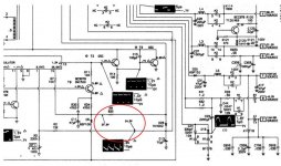
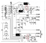
So, I have about 160 ... 162 volts DC on both, C7 and C8.
If it is supposed to be 2x the voltage that I have from the wall, 235VAC,
something is going on there.

Edit:
Checked diodes D1 - D4. None are shorted. They do have around 515 ohm resistance
on the direction where current is flowing.
 
Last edited:
One more set of measures:
154V source we have 225 VDC !
56.7V source we got 86VDC !
21.2V source there is 34 VDC !
12V source - 0 Volts
-6.3V source 0 Volts.

Values that are higher than they're supposed to be are slightly concerning, if they've
damaged something else on the monitor. Hopefully not.

Edit:
Checked all of the diodes (without pulling them from the pcb) and could not find issues there.
Also tried every electrolytic cap with continuity test; probably not ideal way to test them, but
at least there were no shorts on those. I think I will give it a rest until tomorrow.
 
Last edited:
What do you get for the input and output of IC2? Does the LED light up? The outputs are behaving as if there's a short pulling some of the outputs down. With power off and the board connected, check the resistance to ground of the various outputs, particularly the +5.

I suspect that we're only looking under the streetlamp because the light is good (old joke). It could be that the source of the problem lies outside of the PSU and the PSU is simply responding to it. At least you're getting some output, which is a very big thing.
 
Note, that I measured voltage source points when psu was not connected to pcb on the monitor. Only the power switch and the 2cable connector were connected.
But even when the power is connected to the monitor pcb, the green led does not light up.

I will check IC2 input/output when I get home from work.

Edit:
I've tried to study and understand the schematics a bit more. The +5V is generated on another pcb, not on the power pcb.
It needs 12VDC source, otherwise there is no +5V available. Good idea to check resistance to the ground on outputs. Also
very good to check the IC2 voltage regulator, it is probably also a good candidate to having being shorted. It has cooling plate
so it probably runs hot as well.
 
Last edited:
So, IC2 has following values:
input: 24VDC
output: 0VDC

Could overvoltage have destroyed that voltage regulator? Input should have only 14.5VDC.
Or does it need some load at the output? Only other thing that I can see from schematics is C40
that could pull the output to zero. I measured C40 with continuity test and it has 780 ohm resistance,
and therefore it is not be shorted to ground.

Elsewhere in the scematics it is mentioned a couple of places should have 27.3V and 24.5V. These
areas also have 0 VDC.

Other commonly known to be bad are electrolytic caps C11, C13 and C14. None of them are
shorted, yet that does not mean they are ok. I do have ESR meter, I'm thinking if I should pull these
out to test with it.
 

Attachments

  • zero.jpg
    zero.jpg
    100.4 KB · Views: 8
The +5 is just another voltage regulator, so first things first. Start by pulling the 7805 (IC500?) and see if the +12 rises. If that fails, try replacing IC2.

On the schematic, pretty much everything to the left of MM2 deals with drive and regulation. Pin 1 on IC1 is the feedback source. Note that there's a variable resistor, RT1, to "tweak" the output voltage. Don't touch it until you've got all outputs working. You can see where a short would cause voltages to rise on all outputs.

Switching supplies can be difficult to trouble-shoot, but it can be done.
 
Thanks again for your input Chuck.

My setup is as in the attached image. I have only power sw (M3 connector) and
M4 connector connected. Because the power is there on the table, M1 and M2 are not connected.
Thus, +5V regulator IC500 (and circuitry around it) is already effectively pulled. But, is this wrong method
to make measurements? Does IC2 need load before it's output goes up?

If not, 12V regulator IC2 really looks bad. Unless it has some internal safety mechanism, which turns
output to zero, when input is too high? Its input was supposed to be 14.5V and now it is 24V.

Yes, I need to order new 12V regulator to try it out. I think I will make a bit larger shopping list
before ordering anything. At least some (if not all) of the electrolytic caps might be smart to order at
the same order.
 

Attachments

  • pcb.jpg
    pcb.jpg
    100.5 KB · Views: 9
  • setup.jpg
    setup.jpg
    251.4 KB · Views: 10
The 3-terminal linear regulators sometime fail short. This is what I'm trying to eliminate. You've checked all the diodes and capacitors already, right?

And yes, most of these outputs require a load for good regulation. However, that doesn't explain why you see 0V on the output of IC2. Either there's a short on the output side (you can check that by pulling it) or the regulator is bad.
 
Okay. IC2 does not seem to be shorted and IC500 is removed because the power is on the table.
I have checked all electrolytic caps for shorts, there are none, but the rest of the caps I need to still check.
All diodes seem to be okay as well.
 
Wait ! wait a minute!

At a new look, I noticed some residue under C29, so I pulled it out.
Now that it is out, it is pretty clearly leaked!

Also, C29 is directly connected to IC2, 12V voltage regulator and thus we have
a good candidate for one bad boy !
 

Attachments

  • C29_out.jpg
    C29_out.jpg
    187.1 KB · Views: 5
  • C29.jpg
    C29.jpg
    227.9 KB · Views: 5
I don't see C29 connected to anything but L4 on the 56.7 volt rail. So probably not the problem.

How did you test IC2? Here's how I would do it:

Lift the output leg of IC2 and power up the board. Check the voltage coming out of the regulator. It should be about 12V. If not, replace IC2.

If so, then check continuity between the IC2 output pad and ground. It should be a respectable quantity, but not 0 ohms. If close to 0 ohms, check components downstream.

Divide and conquer.
 
> I don't see C29 connected to anything but L4 on the 56.7 volt rail.

Yes, you're correct. I glanced a bit hastely the pcb, the only thing in common with C29 and IC2 is the gnd and they're near
at the pcb and that lead me off to wrong conclusion.

> check continuity between the IC2 output pad and ground. It should be a respectable quantity, but not 0 ohms.

This is what I checked. The resistance was somewhere in the neigbourhood of 700-800 ohms. That looked ok to me.
But pulling the output leg is a good idea. I will try it and share the result here.
 
I revisited Retro Hack Shack, which was very helpful at this point forward:

https://youtu.be/B4u-8s-ID4w?t=2115

This was helpful in 2 ways.

1) I'm not too concerned about the overvoltages that I have mentioned before here.
It is happening, because there is no load. With load, voltages should lower to the right level.

2) The -6.9VDC source has its own ground! Very nice, that Retro Hack Shack mentions this,
because I made the same mistake as he did, measuring the voltage from common ground instead
of isolated ground for this voltage. I'm getting around -11 to -12V here!

So, it really seems the only problem lies with IC2, 12V regulator. I'm going to pull the output leg to make
sure and get a spare for it.

I've already liked Retro Hack Shack video - if there were a 'like more' -button, now would be the time to press it =).
 
Okay,

to evening duties. I pulled the output leg from IC2. sure enough, still zero volts.
But I found out I have scrap C64 motherboard that had 12V regulator in it. I pulled it
and tried on the 5154 power. It gives nice 11,9V now on the output of IC2 !

Then assembly. Power on test gave me green led! step forward!
But the screen remained black and turning on the 5150 did not change that.
After a while I realized that I could turn brightness up. Without the ega video cable connected,
the screen went white. But not 'clean' white but rather kind of vibrating that does not look right.

I also digged out the stuff that came with the monitor. It had another card that looks like EGA card,
I tried with it, but screen remained black. The last option was to try out the trident 8800 card.
I expected to see same blackness, but there was some result! there are text visible, but it's
not so nice like in the still picture. it is running / shaking a bit up and down.

There is still hope, but I think something else is still wrong with the monitor itself.
 

Attachments

  • screen.jpg
    screen.jpg
    231.5 KB · Views: 9
  • cards.jpg
    cards.jpg
    249.1 KB · Views: 9
Yes, very exciting!

Note, that the still image looks better than what it is live. it is vibrating rather annoyingly up/down and the image is also too far left.
Brightness is also at maximum, but it seems quite dim to me.

I had to use the leaked C29 capacitor, since I could not find any suitable value replacement at my stock. It may affect that voltage.
I will be measuring the voltages and post results here.
 
Right, measuring voltages.

I've got: (Should have)

144V (154V rail)
53V (56.7V)
11,9V (12V)
19.9V (21.2V)
-5.8V (-6.9V)

I measured these from the bottom of the main board, just at the contact pins, where
PSU connects to the main board. They seem to be a bit low, generally.

Perhaps adjusting RT1 is needed after all to increase these voltages ?

Edit:
ah, according to the troubleshooting guide, RT1 is for Vertical adjusting. Hmm... it should
ajust the output of IC2. And that's just what I've replaced... and it is actually really close
to the voltage that it should be. On the other hand, image is too far to the left so maybe I could
try this out a little bit.
 
RT1 = V ADJ = Voltage Adjust, not vertical. Yes, tweak it so that voltages are more in line. Note that it will make little to no difference in the 5V or 12V outputs, since those are post-regulated.
 
Aaa, I see.

I tweaked the RT1.
I got the values closer:

153.6V
56.8V
21.5V
-6.4V

If I go lower (to get 21.5 --> 21.2 that it should be) the rest of the values also lower.
I guess I'm close at these values. I noticed a slight improvement in the image - maybe,
but not much impact.

I also tried the knob on the back (V.Size 2). It has big impact, It can make the image
down to almost single line. Adjusting back we're about back where we started.

There is slightly less image vibrating up/down, but still some. I should also try to find where was
vertical adjusting to move the image from left to right.
 
Oh dear,

we are back to completely black screen. The monitor was on for a few minutes and now nothing.
Previously if the EGA cable was not connected, the screen would be white.
 
Back
Top