TerryKing
Member
Hi! I'm so glad to be able to connect with you people!
@VintageVic I did see that thread and I will go over it again. The experiences others have had with real 5154's is invaluable for pointers to causes of symptoms.
@modem7 I have experience with high voltage in broadcast transmitters and other CRT based units. I understand that parts of the circuit boards also have voltages in excess of 100V. Thanks!
I do have good metering and oscilloscopes. I have just ordered an ESR70 capacitor checker from Digikey. I have good soldering stuff and have replaced the usual .1uF AC Line capacitors in 3 units.
I just got one of those XTIDE boards but need to learn how to use it...
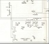
I have the rest of the power supply module capacitors ordered. I do have soft copy of the SAMS Photofact but I need to print and patch it together. And I need to study the schematics! I need to dig my old IBM Manuals out of the barn. I THINK the options/adapters manual does not have the actual 5154 schematic, but maybe has the PGA display?
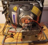
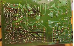
The 3 5154's have these symptoms as of now:
(1) Worked for an hour and then Smoked The Usual Smoke. Replaced the two .1's and the two large 220uF/250V capacitors. Working well now for >40 hours and many restarts. Running on IBM CGA in a 5160 XT. (I need to find an EGA card to test the other scan frequency. ) I must have one Somewhere
(2) Quickly Smoked. Replaced the two .1's and the two large 220uF/250V capacitors. Works now but has horizontal character wiggles that change over time/warmup and not so noticeable after 1/2 hour warmup. [Suggestions?]
(3) Preemptively replaced the two .1's and the two large 220uF/250V capacitors. Dead: power on LED does not come up. Pretty sure the power supply is seated well and all connectors in place. {Where To Start?]
I am trying to get at least 3 complete XT's with two floppy disks and EGA displays working. I'd like to sell two of them to be able to support some other projects.
I have done some work on the original Tandon full height diskette drives, especially methods of cleaning the heads with 99% Isopropyl and clean room paper. But that should be in another thread. What do you think is the best place to discuss that?
The XT's have an interesting history in which they have been taken totally apart down to the system board on the table with the power supply and speaker (Dah Dit-Dit) and then the display and disk cards plugged in to show how it works with those parts, and then reassembled into the case. By middle and high school kids as part of a program that IBM supported me in called "Computer Demolition". I wrote all that up and it was used many many times by me and other IBM volunteers from about 1990..1995. As XTs came out of use at IBM Vermont, I had volunteers remove or wipe the hard drives. Many were donated to schools; some became Computer Demolition candidates with no hard drive. After I 'retired' in 1995 some volunteers kept Demolition running for a few years. In 1995..2000+ my wife Mary Alice Osborne and I did the Demolition for several classes and she did a detailed project with 3rd grade kids about How Computers Work in which they studied and drew diagrams of all the parts.
So these XTs and EGAs have been hibernating in my unheated barn in Vermont for over 20 years. I am trying to wake them up in the world of highly integrated computers with multi-Ghz processors.
Thanks for connecting and I hope to be able to get more of these 'historic' parts working!
Regards, Terry King
...In The Woods In Vermont
The one who dies with the most Parts LOSES! WHAT DO YOU NEED??


