• Please review our updated Terms and Rules here

Issues using Gotek and 1.44 Floppy parallel

_ds_

Experienced Member
Joined
Aug 30, 2023
Messages
54
Hello everyone,

I would like to run my Gotek with my floppy in parallel on my test bench, but the drive on the FDD A connection is constantly addressed, regardless of whether I select drive A: or B: under DOS


Setup:
Gotek: SFR1M44-U100K
Floppy: Mitsubishi MF355F-2490UC


The Gotek is attached to the FDD A connection as shown in the diagram and is jumped to DS1.


If no other floppy drive is connected, everything works fine.


As soon as I do the above on FDD B. If you connect a floppy, the Gotek will always be addressed regardless of whether drive A: or B:.
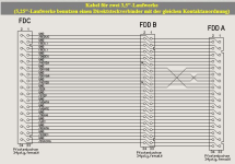
IMG_3095.png

If I flip the drives, i.e. the MF355F on FDD A and the Gotek on FDD B, then it's the other way around (i.e. the real floppy is always addressed and not the Gotek)

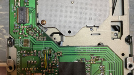
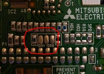
If I remove the metal case from the floppy, I can see 3 pins for a possible definition of jumpers (solder bridges) for DS1 and DS0.

However, this makes no difference if I put a solder bridge from the middle pin to DSO or from the middle pin to DS1 (see next photo).
IMG_3096.png
IMG_3097.png

Has anybody an idea what could be wrong?

BR
Dieter
 
First of all, maybe a silly question, but did you actually configure your computer to have two floppy drives?
  • On PC, XT, and clones there are DIP switches that set the number of floppy drives
  • On AT and clones the configuration is done through CMOS Setup / BIOS Setup.

If you didn't do that, DOS would only address the first drive, and prompt you to swap floppies when you try to switch between A: and B:

The floppy drives on PC/XT/AT are always configured as DS1. It is the twist in the cable that allows addressing two drives separately.
  • Most likely your MF355F came configured as DS1, so restore the jumper or the solder bridge to its original location
  • Check jumper switches on Gotek. They were NOT set correctly (for an IBM-compatible computer) on mine when I've got it.
    • "IBM PC compatibles use a slightly modified interface which places the disk-changed signal on a different pin. To select this interface mode place a jumper at location JC at the rear of the Gotek. The host system may expect the Gotek to respond as 'unit 1': in this case place the selection jumper at location S1 at the rear of the Gotek."
    • Reference: https://github.com/keirf/FlashFloppy/wiki/Initial-Setup#physical-interface
 
Per [here], it is better to say, "the second drive-select position".
Oh, fun!
Most drives I've seen and all FDCs count drive selects from 0. Certainly the OP's drive does.
"the second drive-select" without the drawing seems to be as confusing. Does it mean the one which ends with number "2" or the second available?

I guess, more explicitly:
  • If your drive has jumpers DS0 to DS3, for most IBM PC/XT/AT compatibles use DS1
  • If your drive has jumpers DS1 to DS4, for most IBM PC/XT/AT compatibles use DS2
  • If your drive doesn't have any obvious jumpers, for most IBM PC/XT/AT compatibles you don't need to set anything (you might want to check for solder bridges... maybe)
  • If your drive doesn't have any obvious jumpers, and your PC compatible is a Commodore... pull out your soldering iron, some patch wire, and try to figure out how the heck to set your drive...
 
Might the DS1 and DS0 designators belong to the outlined resistors and not the oval pads. If this is the case the drive is strapped for DS1. If the "DS1" resistor measures 0 ohms then it's likely a jumper.
 
Sorry guys for the late replay.
Was a busy week....


Anyway.


No, I have not configured a second floppy on my mainboard/bios.
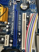
To be honest, I dont have a vintage mainboard, it is more or less a quite new one. One of the last available mainboards with a floppy connector (ASUS N68-S3 UCC ==> Mainboard)

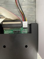
I did what sergey suggested, to set JC jumper on gotek device and keep DS1 on Gotek configured.
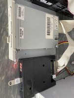
The Gotek is/was connected on FDD A (so after the twist) and the Floppy is on FDD B ( before the twist - right after the connector from FDC on the mainboard)

So I still have the issues that I cant operate two drives at the same time.

BR
Dieter


IMG_3131.JPGIMG_3129.JPGIMG_3130.JPG
 
I also had this expecation already, since I could not find any configuration positons within BIOS menu.
So I have now to live with this single floppy solution without implementing a hardware based switching solution.

But could somebody recommend my a current mainboard, which is available on the market (like amazon) and would support two or more floppys or should I bug a "real" external Floppy Drive Controller board and mount it into the PCI Bus on my mainboard?
 
The late-age boards did not support a second drive in hardware, and consequently removed the BIOS support for them as well. So even replacing the floppy controller won't get you that support, and I have never heard about PCI floppy controllers either.

So I guess you are out of luck with any "modern" mainboard...
 
I think the two-drive support on motherboards pretty much vanished after Socket 754 and P4. If there are later boards, I'm not aware of them. My Socket AM3+ board does support a single floppy.
 
Back
Top