Dwight Elvey
Veteran Member
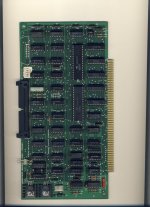
What controller are you using?
Dwight
Dwight
| VCF West | Aug 01 - 02 2025, | CHM, Mountain View, CA |
| VCF Midwest | Sep 13 - 14 2025, | Schaumburg, IL |
| VCF Montreal | Jan 24 - 25, 2026, | RMC Saint Jean, Montreal, Canada |
| VCF SoCal | Feb 14 - 15, 2026, | Hotel Fera, Orange CA |
| VCF Southwest | May 29 - 31, 2026, | Westin Dallas Fort Worth Airport |
| VCF Southeast | June, 2026 | Atlanta, GA |
What controller are you using?
Dwight

The 765 "Read Track" operation looks for DAMs and just reads the data from index to index. So if you have a 16-sector track, you get "only" 16 sectors of data; no gap bytes, address headers, etc. As a matter of fact, the "Read Track" is useful for recovering data when the IDAMs are corrupted, because those are ignored.
You can "trick" the 765 into reading raw data after a fashion by giving the command a larger-than-actual sector size. Since the IDAMs are ignored, the sector size in the command overrides any recorded in the address headers. But you don't get any re-sync of the data separator on subsequent sectors after the first, so the remainder will probably be gibberish.
The WD 17xx/27xx is a true "read track" in that you get everything.
The 765 has a read track operation. You might take a good disk and do a read track. Then take one that you tried to format and also do a read track. One can compare gaps and such that way. You might also take a look at the index signal from the drive. The Format instruction requires a clean index signal.
Dwight


Yes, the format command writes from index-to-index. So if you don't have a good index signal, you're not going to get a good format.
The index logic on the FDC is edge-sensitive. So as long as there's a clean bounce-free edge on the pulse, you're golden.
")
Also, make sure that the head-load mechanism is operating correctly. You should be able to hear the solenoid kick in when the drive is selected.
Also make sure you have enough delay for track to track before you tell it to write. Reading is some what fault tolerant. It will usually wait until it gets a clean header an then read.
Step delay is usually something you have to set up.
Dwight
Also, make sure that the head-load mechanism is operating correctly. You should be able to hear the solenoid kick in when the drive is selected.
No, it's not.
This is the mistake that I made with the first floppy driver I wrote a very long time ago. It would read just fine, but would corrupt the occasional write.
Here's the scoop--the head load/unload and the positioning mechanism are mechanical systems. As such, there are resonances that slowly decay with time. When the head is loaded or the head is moved, it doesn't settle down immediately and continues to vibrate a bit, jeopardizing contact with the medium. You have to build in delays in the area of 15-30 milliseconds for both.