• Please review our updated Terms and Rules here

Lisa video fault

Gary C

Veteran Member
Joined
May 26, 2018
Messages
2,302
Location
Lancashire, UK
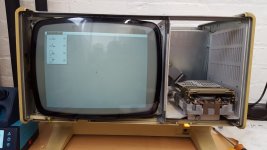
So, this thread is looking for help to diagnose a Lisa video fault.

I know it is probably capacitors (!) but I would like if I could, hopefully engaging Hugo's expertise to step through the fault and learn something about how the circuit works and maybe it will help others.

So symptoms.

The machine works and video is present on the rear connector, but the screen has no High voltage present in that there is no static on the tube (it was working a few weeks ago)

Drawing here https://archive.org/details/bitsavers_applelisaho_259795

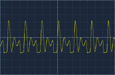
Knowing the high voltages are created from the horizontal drive, measuring at Q5 collector I get
View attachment 1264197
20.7V peak & 22.7 kHz


To the neck, on red I just get 41V DC ?

I also note that at the flyback (violet) which should be 28V, I am only getting 7V from the regulator U1.

How does that part of the circuit work ? Q5 turns on and off to oscillate the flyback, with the 28V being the supply ? The regulator is hot
 
Last edited:
The 78M24 regulates the 33v at the edge connector to 28v and passes that around everywhere, so consider that your B+. There is also a +12v source entering into the analog card. Make sure that is present, but it should since the rest of the Lisa seems to be working.
It's only a 500ma regulator so if you have a leaky cap that's gonna load it pretty hard.
Missing 12v you'd know because you would have no neck glow but the fact you have an oscillator at flyback pin 1 and presumably 28V at flyback pin 3 I would suspect that either C8 is leaky or CR3/CR4 has an issue.
 
I could not open the image you attached,

The voltage regulator is likely in shut down mode due to the H output stage drawing too much current.
One way to confirm that is to disconnect the collector of Q5 and seeing if the voltage regulator normalizes.

If the H output stage is the culprit, a number of failures can cause it to do this. Defective H output transformer, defective Q5 or any of the diodes in the area shorted, Any of the filter caps shorted etc.

Also, if the drive waveform that Q 5 receives is the incorrect duty cycle or frequency can also do it.

Ideally a scope recording of the H drive signal as well as the collector voltage of Q5 will help.

How it works:

Generally Q5 is switched on about 1/3 the way into active H scan time. When the CRT beam as about on the middle of the screen, Q5's collector current is zero and the current in the H yoke coils is zero. But then the current starts to rise at a very rapid rate, because you have the inductance of the yoke switched by Q5 across the power supply.

The rate of rise of collector current is near linear and many thousands of amps per second. This scans the CRT beam from the center to the right hand side of the CRT's face. However, after about 30 uS (approximately) Q5 is switched off by the driver transistor Q4 being driven into conduction, cutting off Q5's base current. (by the way Q5's base current was derived from stored magnetic energy in the small driver transformer's core T1). The collector current of Q5, due to the short duration of the time Q5 is turned on for, only would peak to around 3Amps. (unless of course the drive waveform was abnormal). The average current consumption from the power supply is much lower, usually under an amp due to energy recovery.

Once Q5 is cut off, flyback begins, this is a relatively un-damped resonant process where the inductance of the H output transformer and the yoke rings (oscillates) in conjunction with the self and lumped tuning capacitance C25. The energy that drives this is the magnetic field stored in the H output transformer and yoke fields at the end of H scan when the beam was fully deflected to the R hand side. Only one 1/2 cycle of the oscillation is seen (typically about 10uS wide at its base), the voltage peaks up to some 200V or more on Q5's collector.

Only half a cycle of oscillation is seen, because as it attempts to drive Q5's collector negative, the energy recovery diode (damper diode) CR9 conducts. This occurs when the magnetic field has reversed directions and the CRT beam is now on the left hand side. The stored energy in the field then is returned via the damper diode CR9 to the power supply and again this is in a fairly linear manner and this scans the left side of the raster and the process repeats. This is why this system is called "energy recovery scanning".

Therefore, there are essentially two modes of operation involving the H output transformer and Yoke, one heavily damped during scan time where the transformer is acting in a typical transformer mode, the other a resonant mode, during flyback time.

Apart from scanning the horizontal component of the raster with a linear scan and a rapid flyback of the CRT's beam, some energy is extracted from the H output transformer and it can be extracted during scan time or during flyback time. For example the stepped up EHT voltage is acquired during flyback time (the peak voltage rectified) Often other voltages from the transformer are peak rectified too, In other cases the voltage is acquired during active scan time, for example via CR4 to run the video output stage.

Generally, it is diagnostic to look with the scope at the collector waveform of the H output transistor (HOT) Q5 always use the x 10 probe in the case of small monochrome VDU's. In cases where there are shorts in the output transformer windings, or overload on the flyback peak etc, it gets a characteristic look. For color sets though, the peak collector voltage on the HOT can be in the 1kV region and they need a 1.5 to 2kV rated x100 probe to measure safely without damaging the scope or probe.
 
Last edited:
It is interesting that the WIDTH potentiometer is on the 0V/common pin of the +24V regulator. Ugh!

Dave
 
Since the rate of rise of H scan current with time is V/L amps per second where V is the power supply voltage and L the combined inductance of the H yoke coils an H output transformer, adjusting the power supply voltage directly affects the width of the scan. It affects a lot of the other circuits too, to some extent, like the height (vertical scan amplitude), but less and these have other controls. So in this case they simply called it a width control, it simply adjusts the regulator output a little to get it from 24 to 28V.

The other common method to adjust the width was with a variable inductor in series with the yoke (often along with the S correction capacitor and magnetic linearity coil), but also parallel can work too, and they labelled that one coarse width.
 
I think your probably right about the regulator which is why I haven't swapped it for the only one I have that has a 1A limit rather than the 500mA of the fitted unit.

I will disconnect Q5 first.
 
The scope trace is diagnostic of the basic problem. After flyback, there has been insufficient energy stored in the core of the output transformer prior to flyback. Not enough to keep the damper diode in conduction.

Typically this can be from overload on one of the output windings, or short in one of the windings in the transformer or yoke. See below how to test down this route.

However there is something odd about the recording in another way. If you look at it, the oscillations don't get clamped out until very late in the scan time. This also suggests that the drive waveform (Horizontal drive) might have the wrong duty cycle too. So for that we need a dual trace scope recording of the collector of Q 5 again with the Horizontal Drive signal on the other trace. Even if that was the case though, it would not increase the current consumption of the H output stage.

If we confirm that the H output stage is overloading the regulator with high current drain(as I think it is) then we have to find out why.

This involves a series of tests/experiments one at a time. Because it could be shorted diodes or filter caps.(or the transformer itself).

One at a time, disconnect: (and check if the high current drain drops away and the voltage regulator output recovers to 28v)

C26 , the 2uF yoke coupling capacitor
CR11
CR4
Also, the transformer EHT winding can be overloaded if the EHT rectifier built into the transformer has shorted out. For this test you need to remove the EHT clip/cap from the CRT. But don't just leave it dangling, Find a small deep glass jar, put it inside that and also tape the cable so that it cannot fall out. It needs to be very well insulated for the test, you cannot just wrap some insulating tape around the clip, it could arc through.

Only after external loads on the transformer are eliminated could we start to get suspicious of shorted turns in the transformer. If the EHT rectifier has gone leaky, it is possible to fix it by adding an external one in the EHT lead feeding the CRT.
 
Last edited:
Scrub that. Things seem to have changed.

Even with CR disconnected, voltage has fallen to 2.2V. By disconnecting the yellow wire to the flyback, I get my 28V back.

Update

Q5 appears to have failed. C to E is conducting forwards and backwards and B to E is conducting forwards & backwards with my meter on diode test. However this might be a symptom rather than a cause and may explain the change in test results, ho hum.
Something has happened, but if Q5 was shorted out, you could not have recorded the collector voltage waveform you had on post #6

I assume you are testing Q5 out of circuit, or with the collector disconnected as I suggested ? And with Q5 out of circuit, or collector disconnected, the 28 volt regulator output recovered confirming excessive current drain by the H output stage ?

(If Q5 is tested in circuit by mistake, the B-E junction will "appear" to be shorted, because of the low DCR of the driver transformer secondary winding and the C-E will also "appear" to be shorted because of the low DC resistance of the transformer primary and the +28V rail adopting a low resistance to ground with the power supply not running)

If Q5's junctions have now truly melted and it is shorted on out of circuit testing, it is possible that with the high range collector currents, due to the fault, that Q5 finally failed. If that is the case, we will need to fit another Q5 and re-establish the recording that you had in post #6 on Q5's collector, and keep looking for the source of the fault.

Also, most likely if CR4 had failed and or the circuit it feeds drawing excessive current, the series 22R 1/2W resistor would have smoked, so probably CR4 and its associated circuitry is ok.
 
Last edited:
Q5 tested out of circuit and is toast. It did test ok originally out of circuit. Noticeable at first the voltage was falling to 7V, then when Q5 failed it was dropping to 2V.

For interest, what is the purpose of C8 & R15 ? on flyback current flows via CR4 to provide the voltage modulated by the video signal to the tube with CR4 to stop it collapsing ?

Spares on order.
C8 is simply pre-charged to 28V by R15 in about 100mSec, so there is less initial load on the Flyback transformer after start up, then after that CR4 charges C8 to a higher voltage than 28V.

Then they have the series diode CR3, the purpose of that is to store charge on C7 at turn off, this helps prevent the turn off or afterglow spot, by helping to keep the CRT's cathode positive for a time after turn off, helping to extinguish the beam current at turn off.
 
BTW I am reading and re-reading your write up while analysing the circuit diagram and while I did basic TV repair as an apprentice and DC transient analysis at University the dynamic intricacy of these circuits is fantastic.

Thank you, its broadening my understanding Tenfold.
 
BTW I am reading and re-reading your write up while analysing the circuit diagram and while I did basic TV repair as an apprentice and DC transient analysis at University the dynamic intricacy of these circuits is fantastic.

Thank you, its broadening my understanding Tenfold.
For the H output stage, the circuit idea is very old. It dates back to the early 1930's.

The basic concept for energy recovery scanning or efficiency scanning was first proposed by Alan Blumlein , the inventor or stereo audio.


But, much of the research work that made it possible was done at RCA labs in the 1940's by Otto Schade. His papers on the topic are among the best works I have ever seen.


He was a genius with electronics, initially unrecognized ( somewhat analogous to the guitarist from the band Chicago, Terry Kath ) and not a household name, later his family tried to give him the public credit he deserved.

( to understand what I mean there about Terry Kath have a look at 25 or 6 to 4:

)

The idea of energy recovery scanning being that the energy required to scan the R side of the raster is stored in the magnetic field of the yoke and output transformer at the end of H scan on the R side. Then after flyback which is a relatively undamped oscillation of half a cycle and about 10uS wide in many VDU's, though EGA ones have a very short flyback, this reverses the polarity of the field and that positions the CRT's beam on the left side, then the magnetic field energy is returned, sent back to the power supply as damped current, via the damper diode, to scan the left side of the raster.

Therefore, the energy consumption is low, because it is only that due to energy losses, largely in the circuit resistances. The analogy being like a pendulum only requiring enough energy to overcome losses. The damper diode is sometimes referred to as the energy recovery diode, or efficiency diode. Later the basic idea was also used in various forms of SMPS's and "flyback" power supplies.

Any additional circuit resistances tend to generate heat and degrade the scanning linearity. This is why the yoke coupling capacitor (S correction capacitor) must be a very low ESR type, typically less than 0.1 Ohms in a transistor system. Also, in the transistor based system, the output transistor acts as a saturated switch. In vintage tube based systems, the voltages are higher and the currents lower, for the same deflection power, and resistance in the system was less problematic with energy losses.

The other advantage is that the undamped flyback peak is transformed up to generate the CRT's EHT voltage, so you get twice as much bang for your buck, scanning and the EHT and other auxiliary voltages from the H output transformer, to run the video output stage and other CRT electrode voltages too. Before this was done, TV's for example, in the 1939 era had line transformers to get the EHT and these were very dangerous power supplies as they could source more than 30mA current.

The idea doesn't work for the vertical output stage because of the much lower frequency and other proportions there of inductance and resistance. Generally the vertical output stage remains very similar to the audio power amplifier, with an extended low frequency response.
 
Last edited:
Q5 replaced and back to 28V falling to 7.5V.

repeated the removal of CR4 and no change.

Unplugged horizontal coils and 28V present with around 10kV on the EHT line so flyback is working.

The drawing gives the horizontal coil as 0.62ohm, battery flat on my fluke but the workshop meter gives 1ohm.

With L3 out of circuit,

working-L3 out.jpg

It works. Thing is, L3 measures 3 ohm and while it is its reactance that matters, I would have thought this roughly indicates no shorted turns ? Any rough DC resistance figures for this inductor ? From a DC current draw of course, C26 prevents this and with a basic test using a meter on resistance, seems to be ok but I wonder if this is worth replacing too.

I'm sure the picture makes any video engineers teeth itch with obvious bowing at the sides but I need to decide if its worth trying to find a replacement for L3.

The flyback and the scan coils all look good though, which is a relief.

Interesting that on the later revision of this board, L3 has been removed.

Hugo, thanks for the info very interesting.

EDIT

Just realised (of course) with the H coil disconnected, L3 was still in circuit so all I have done is reduce the loading in this leg.
I believe the scan coil is ok (DC resistance appears to be correct).

So, C26, L2, R46. L3 or of course the source of the 28V, the 78M24 might be coming into limit early ?
 
Last edited:
Well, L3 must have shorted turns. Unlikely the yoke does, or you would not have such a normal looking slightly undersizse H scan with no L3.

This lowers the combination of L3 and the H yoke coil inductance. Therefore, the current will rise much higher in scan time than it would normally, and on top of that the stored energy is very low. This accounts for the collector voltage waveform you had, suggesting limited stored magnetic energy in the H yoke coils and horizontal output transformer. Re-check the collector voltage waveform of Q5 with no L3, it should be just a single flyback pulse.

Coils to adjust scan width, in parallel with the H yoke coils, are not as common as ones in series. They still work though.

Having found that L3 is defective, I would not be 100% happy about that finding, and try to find out why. I suggest unwinding L3, if possible, and try to find out how it acquired shorted turns.
 
Back
Top