• Please review our updated Terms and Rules here

Lisa video fault

Unwinding isn't going to be that practical, the shellac is really hard.

A replacement looks difficult too. Given that Apple themselves got rid of it, I probably need to look at the supporting circuit changes when this inductor was removed. Its noticeable they also changed the 78M24CT with a 500mA limit to a 7824CT with a 1.5A limit.

Though a bit buggered as the notes state that 'L2 value changed' but not from what to what.

Ah well.
 
Last edited:
I've been very grateful to follow this thread. Having never unwound a broken inductor (or a working one), what sorts of things might you find and what causes would you infer from them? Feel free to refer me to some other resource if one is available.
 
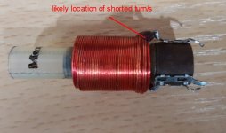
What sort of resistance would you expect from this coil ?


The 1.1 to 2.8mH variable inductor, will be expected to have a higher DC resistance than the H yoke coils, but if it was too high, it would not be effective. You can estimate it from the geometry of the coil and the wire diameter if you can measure that, I could calculate it for you. Lower DC resistance is better as there are less losses as heat.

One thing that could work is to buy a fixed ferrite cored inductor, say around 1.5mH, rated at, at least a few amps, The kind of thing used in SMPS filters, or wind one, on a ferrite core, connect that in parallel with the H yoke coils and see if the total scan width is about right, then you can adjust the regulator output voltage a little with the other "width control" ( 28V power supply voltage) there to get it about right.

A ferrite core like this will work and you can just wind it with the number of turns required to get the width right:


Can you post a photo of your defective coil ? Do you have an inductance meter, or a signal generator and scope, to check that this inductor is definitely the problem, it does seem to be, in that removing it eliminated the problem.The collector voltage of Q5 was previously grossly defective indicating limited magnetic field energy storage, characteristic of a shorted inductor in the H transformer or yoke circuit.
 
What risks are there by taking turns off one at a time until the reading changes?
It looks in excellent condition, so it can't be one of the inner turns.
 
That coil looks to be in good physical condition, and a DC resistance between 2 and 3 Ohms not looking unreasonable. It doesn't look overheated, still even with just 1 shorted turn it would generate the fault and its resistance would appear close to normal

The most likely place a shorted turn/s would not be between the regular wires that lie side by side or even directly on top of each other, but where the start and finish of the wires exit the coil and pass to the tags and cross the other wires perpendicularly. Have a look with magnification where the wires exit the winding and check if there is any area that looks suspicious for a short. It might be possible to fix it.

Also this coil would be a easy candidate for a rewind.

Still it would be nice to measure its inductance.

I cannot see, is that a blob of black glue near one of the solder tags ? Glues are notorious for degrading enamel insulation, the same problem causes shorted turns in deflection yokes, there could be a short under that, remove that glue, if it is glue, for inspection. If that is the finish of the winding, and the short is there, you can remove 5 or 10 turns to eliminate the damaged insulation and you will still have plenty of adjustment range.

Don't forget on Ferrite slugs which have a hex hole (or even a slot) never use a metal Allen key or screwdriver, only ever a plastic tool, or the slug will break. often splitting on its long axis and lock in the threads. (I have posted a method in the past, to remove them, if that happens)
 

Attachments

  • Coil1.jpg
    Coil1.jpg
    95.8 KB · Views: 2
Last edited:
The problem is the windings are stuck together too and the blob is really hard varnish but I will give it a go.
 
The problem is the windings are stuck together too and the blob is really hard varnish but I will give it a go.
C'mon Gary, grab the glued area in the jaws of some side cutters and tear it away from the surface, unwind some of the turns. If you think you have cleared the short, connect the coil back in and see what happens.
 
Unwound and no obvious short. There is some lacquer damage but that looks like it came off as it was unwound but who knows.

It is possible maybe that the design is marginal and why the coil was removed in later versions.

Will look for a replacement.
 
Unwound and no obvious short. There is some lacquer damage but that looks like it came off as it was unwound but who knows.

It is possible maybe that the design is marginal and why the coil was removed in later versions.

Will look for a replacement.

There is no "who knows". It is up to us to figure it out and know. It is like Yoda's remark: No try, just do.

After you have removed 5 to 15 turns, reconnect the wire & put the coil back in (or link it in with wires). Is the fault still present, or not ?

I doubt if the design was marginal, because the collector voltage recording of Q5, showed a catastrophic loss of inductance.
 
Last edited:
I say 'who knows' because I have varnish missing but it might have been lifted as I removed the blob. At the moment, the coil has got visibly shorted turns but I can't positively say it was me or a fault.

Rather than piecemeal test, I think it might be 'simpler' to rewind (oh fun, used to wind custom bobbins for thermistor instrument loops) or find a replacement.

Replacements though, seem to be hard to find.
Typically, Width coils, Linearity coils, H output transformers and yokes were proprietary items unique to the particular VDU. So often, as a spare part, are very hard to get. The only easy way to find them is from a parted out unit.

Still, with this one, a rewind is a dead easy task. Measure the wire diameter. Buy new wire on ebay, and rewind it with the same (close to) number of turns, and all will be well.
 
He was a genius with electronics, initially unrecognized ( somewhat analogous to the guitarist from the band Chicago, Terry Kath ) and not a household name, later his family tried to give him the public credit he deserved.

( to understand what I mean there about Terry Kath have a look at 25 or 6 to 4:

)
Although slightly off-topic I must violently agree with you on the subject of Terry Kath. Those of us who were aspiring rock guitarists in the late 60s / early 70s regarded him as being in the same pantheon as Jimi Hendrix. Hendrix himself was somewhat in awe of Terry's talent and had plans to record with Chicago that were cut short by his untimely death.
 
Although slightly off-topic I must violently agree with you on the subject of Terry Kath. Those of us who were aspiring rock guitarists in the late 60s / early 70s regarded him as being in the same pantheon as Jimi Hendrix. Hendrix himself was somewhat in awe of Terry's talent and had plans to record with Chicago that were cut short by his untimely death.

Yes, I cited Terry as an example, similar to Otto Schade, in that they were both geniuses in their respective fields, but during their time were not recognized as much as they should have been, somehow a little overlooked. Then, many years later, their families sought to get them the public recognition that they well deserved. The two people had that thing in common.
 
The long tailed pair and the common mode rejection ratio were a central topic in many lectures.

We have changed onto the subject of differential amplifiers ?

Interestingly these backdate to the time of tubes. There is a very good description of these both for Tubes and Transistors in Millman and Halkias's book, Electronic devices & circuits. Both significantly benefit with a constant current stage in the cathodes or emitters.

One further development of this was to add another pair of transistors and cross the collectors over. This idea created the 4 quadrant multiplier, often called the Gilbert Cell.

This could be used in mixers, modulators, phase detectors , voltage multipliers etc. Probably one of the most versatlie transistor configurations ever created (look inside the IC MC1496).

Interestingly Gilbert patented it in the early 1970's, but the Swiss company Nagra were already using it prior to this, as a phase detector for the capstan servo in their portable tape decks (so that you could Xtal control the speed, and stop the lip sync drifting off adding recorded audio to films). Tektronix got onto the design too and used it in the front end of their scopes. It also turned out that the circuit configuration had been invented about a decade before in the early 1960's, by a fellow named Jones, but due to the obscurity of his work, he never got the credit, but I call them Jones multipliers in his honor.

Tek also figured out that you could use the configuration, because of its 4 quadrant nature, to accurately phase reverse a signal. So in their scopes, the late model 464 for example, they used it not only to convert the single ended probe signal to differential (for the vertical amplifier chain) but also for the INV (invert function) to invert the the signal for channel 2 when the scope user wanted that, very clever.
 

Attachments

  • INV.jpg
    INV.jpg
    107.7 KB · Views: 2
  • MC1496.jpg
    MC1496.jpg
    50.9 KB · Views: 1
Last edited:
It was in relation to Mr Blumlein's page you posted.

Interesting reading.

Anyway. Wire ordered and it needs it because the width control is at its stop at the moment.
 
Back
Top