• Please review our updated Terms and Rules here

Macintosh classic ii vertical collapse

Lololobolosse

Experienced Member
Joined
Oct 29, 2021
Messages
88
Hello, i have a faulty macintosh classic ii with vertical collapse, what schould i look for on the analog board ?
Considering the hard drive is spinning up means the problem might only be on the high voltage part of the board ?
Theres also no boot signs of the motherboard.
 
Vertical scan collapse is not an uncommon fault in TV's or VDU's. The vertical scan stage is responsible for driving a current through the yoke's vertical coils. Typically it has a sawtooth like form for a linear scan, and a rapid flyback for V retrace.

Essentially the output stage is a power amplifier and more often than not, the drive signal for it comes from a vertical oscillator, which is synchronized to the incoming vertical sync pulse. Though, some computer VDU's don't have the vertical oscillator and instead use the vertical pulses and horizontal pulses from the computer directly. If the VDU has a vertical hold control, and H hold control, then you know that is has its own internal scan oscillators and the scanning can run independently from the computer sync pulses, much like a TV not receiving a signal, the H & V scans are still working.

In many VDU's they started out as discrete transistor designs, for the scan oscillators and discrete transistor output stages for the power amplifier. The vertical output stages are very similar in their design to a power audio amplifier. Later, the manufacturers moved to IC's which contained the oscillators and power amplifier in one package for the vertical scan system.

They often pushed these a little hard without adequate heat sinking and vertical output IC's can have a penchant for failing. Sometimes they used an IC and added a transistor output stage if the IC was not up to the required deflection power, but in small VDU's, it is often just the one vertical osc & deflection IC in charge. That could be one cause, a failed IC or transistor/s.

Other times there are fusible resistors in series with the power voltages fed to the deflection stages (or IC's) or filter inductors these can go open circuit killing the scan that way. Or bad connections to the yoke coil or fractured connection elsewhere. Usually in the case of defective electrolytics, the scan is not totally dead but low amplitude & distorted. So if the V scan is totally dead, not too likely to be a capacitor problem.

In any case, the usual protocol is to get the schematic , and start testing with the meter and a scope, it is usually easy to work out why the vertical scan has failed.

Can you post the schematic ?
 
If you haven't already, reflow ALL solder connections on the analog board before you start troubleshooting it, or you may end up chasing your tail.

The heat generated inside compact macs bakes the analog boards to death and causes dry/cracked joints. I'd also recommend hosing down the potentiometers in Deoxit Gold and wiping them back and forth a few times, then reset them to their original positions.

You should also turn the brightness adjustment all the way down (if possible) to avoid burning the screen.
 
Vertical scan collapse is not an uncommon fault in TV's or VDU's. The vertical scan stage is responsible for driving a current through the yoke's vertical coils. Typically it has a sawtooth like form for a linear scan, and a rapid flyback for V retrace.

Essentially the output stage is a power amplifier and more often than not, the drive signal for it comes from a vertical oscillator, which is synchronized to the incoming vertical sync pulse. Though, some computer VDU's don't have the vertical oscillator and instead use the vertical pulses and horizontal pulses from the computer directly. If the VDU has a vertical hold control, and H hold control, then you know that is has its own internal scan oscillators and the scanning can run independently from the computer sync pulses, much like a TV not receiving a signal, the H & V scans are still working.

In many VDU's they started out as discrete transistor designs, for the scan oscillators and discrete transistor output stages for the power amplifier. The vertical output stages are very similar in their design to a power audio amplifier. Later, the manufacturers moved to IC's which contained the oscillators and power amplifier in one package for the vertical scan system.

They often pushed these a little hard without adequate heat sinking and vertical output IC's can have a penchant for failing. Sometimes they used an IC and added a transistor output stage if the IC was not up to the required deflection power, but in small VDU's, it is often just the one vertical osc & deflection IC in charge. That could be one cause, a failed IC or transistor/s.

Other times there are fusible resistors in series with the power voltages fed to the deflection stages (or IC's) or filter inductors these can go open circuit killing the scan that way. Or bad connections to the yoke coil or fractured connection elsewhere. Usually in the case of defective electrolytics, the scan is not totally dead but low amplitude & distorted. So if the V scan is totally dead, not too likely to be a capacitor problem.

In any case, the usual protocol is to get the schematic , and start testing with the meter and a scope, it is usually easy to work out why the vertical scan has failed.

Can you post the schematic ?
Here are the schematics i found for the macintosh classic ii
 

Attachments

  • Macintosh-Classic-Classic-II-Schematic-bomarc.pdf
    7.1 MB · Views: 5
If you haven't already, reflow ALL solder connections on the analog board before you start troubleshooting it, or you may end up chasing your tail.

The heat generated inside compact macs bakes the analog boards to death and causes dry/cracked joints. I'd also recommend hosing down the potentiometers in Deoxit Gold and wiping them back and forth a few times, then reset them to their original positions.

You should also turn the brightness adjustment all the way down (if possible) to avoid burning the screen.
I will reflow all solder connections today. and does someone have a pinout or something similar to check the voltages of the analog board ?
Since the hard drive is spinning up i believe the 12v rail is okay but theres not boot chime or activity so there might be a problem on the 5v rail
 
I prefer not to just start reflowing solder joins unless there is an obvious visible fracture, while it might be one, it might not. If its starts suddenly working, you won't really be sure where the fault was, and it can come back to haunt you. It is better to disturb as little as possible to find the fault with diagnostic testing and home in on the exact cause than relying on luck.

The vertical IC is the TEA2037. There is not a lot to it. It contains both vertical and horizontal scan circuits, but the designers have not used the horizontal parts. It has a vertical oscillator, so it should still be running even if the vertical sync pulse is missing.


Check that the IC is receiving the supply voltages on pin 2, 7 and check the voltage on pin 16 with the meter. Check that resistor RF13 is not open circuit as an initial start.

Sometimes there is a tendency for people to blame an IC when it is in charge of most of the functionality of the sub-circuit. While it might be faulty, it is better first to try to rule out any faulty parts or power supply abnormalities, or the IC might get needlessly replaced. If all the components (resistors, capacitors & diodes) around the IC are normal though, and the correct power supply voltages present and there are no fractured connections and the V yoke coils and connections are good, only then think about replacing the IC.

Do you have a scope ? If so, we could scope the vertical oscillator waveform on pin 1 of the IC and see if that was running too.

(in this design there is no V hold control, they just fixed set the V osc free running frequency with the 820k & 180nF capacitor)

It was repairing this, and because I'm a big fan of spare parts, unless something very obvious sticks out soon, I would order a spare IC because they are cheap and they can take a while to come in the mail, and it would not be a disaster if it was not used, but it might end up saving some time:

 
Last edited:
I prefer not to just start reflowing solder joins unless there is an obvious visible fracture, while it might be one, it might not. If its starts suddenly working, you won't really be sure where the fault was, and it can come back to haunt you. It is better to disturb as little as possible to find the fault with diagnostic testing and home in on the exact cause than relying on luck.

The vertical IC is the TEA2037. There is not a lot to it. It contains both vertical and horizontal scan circuits, but the designers have not used the horizontal parts. It has a vertical oscillator, so it should still be running even if the vertical sync pulse is missing.


Check that the IC is receiving the supply voltages on pin 2, 7 and check the voltage on pin 16 with the meter. Check that resistor RF13 is not open circuit as an initial start.

Sometimes there is a tendency for people to blame an IC when it is in charge of most of the functionality of the sub-circuit. While it might be faulty, it is better first to try to rule out any faulty parts or power supply abnormalities, or the IC might get needlessly replaced. If all the components (resistors, capacitors & diodes) around the IC are normal though, and the correct power supply voltages present and there are no fractured connections and the V yoke coils and connections are good, only then think about replacing the IC.

Do you have a scope ? If so, we could scope the vertical oscillator waveform on pin 1 of the IC and see if that was running too.

(in this design there is no V hold control, they just fixed set the V osc free running frequency with the 820k & 180nF capacitor)

It was repairing this, and because I'm a big fan of spare parts, unless something very obvious sticks out soon, I would order a spare IC because they are cheap and they can take a while to come in the mail, and it would not be a disaster if it was not used, but it might end up saving some time:

On pin 2 i get 12v
On pin 7 15v
And on pin 16 10v
 
I prefer not to just start reflowing solder joins unless there is an obvious visible fracture, while it might be one, it might not. If its starts suddenly working, you won't really be sure where the fault was, and it can come back to haunt you. It is better to disturb as little as possible to find the fault with diagnostic testing and home in on the exact cause than relying on luck.

The vertical IC is the TEA2037. There is not a lot to it. It contains both vertical and horizontal scan circuits, but the designers have not used the horizontal parts. It has a vertical oscillator, so it should still be running even if the vertical sync pulse is missing.


Check that the IC is receiving the supply voltages on pin 2, 7 and check the voltage on pin 16 with the meter. Check that resistor RF13 is not open circuit as an initial start.

Sometimes there is a tendency for people to blame an IC when it is in charge of most of the functionality of the sub-circuit. While it might be faulty, it is better first to try to rule out any faulty parts or power supply abnormalities, or the IC might get needlessly replaced. If all the components (resistors, capacitors & diodes) around the IC are normal though, and the correct power supply voltages present and there are no fractured connections and the V yoke coils and connections are good, only then think about replacing the IC.

Do you have a scope ? If so, we could scope the vertical oscillator waveform on pin 1 of the IC and see if that was running too.

(in this design there is no V hold control, they just fixed set the V osc free running frequency with the 820k & 180nF capacitor)

It was repairing this, and because I'm a big fan of spare parts, unless something very obvious sticks out soon, I would order a spare IC because they are cheap and they can take a while to come in the mail, and it would not be a disaster if it was not used, but it might end up saving some time:

I have a scope but it has no probes so sadly i cant work with it
 
I prefer not to just start reflowing solder joins unless there is an obvious visible fracture, while it might be one, it might not. If its starts suddenly working, you won't really be sure where the fault was, and it can come back to haunt you. It is better to disturb as little as possible to find the fault with diagnostic testing and home in on the exact cause than relying on luck.

Unless you have a scanning electron microscope, you can't be sure there are no cracks in the joints, because they can be microscopic, but cause problems all the same. The goal is to make sure there are no phantom faults caused by microscopic cracks that can change literally by bumping the table the machine is sitting on, or even by thermal cycling. Every single analog board I've ever worked on has had cracked and dry solder joints that have caused real problems.

These failures are notorious in all Compact Macs due to the heat and having extremely poor ventilation. It's LITERALLY the first step you should do when working on any analog board, even of known origin, because of all of the heat stress. Telling someone not to do it is just terrible advice and will needlessly complicate and extend the potential repair time.

An easy and not so scientific test is to take a plastic implement and tap the back of the analog board moderately while the machine is running. If you see any glitching on the screen, or voltages start to change, there's a bad joint somewhere on the board. It could be a connector, it could be a component.

Well that maybe so, and it is a reasonable idea to slightly flex the board too, but like I said, I inspect the soldering, and would re-solder any obviously broken or suspicious looking connections.

But, initially at least, I never do it globally across a whole board (nor do a global re-cap for that matter either).

The reason is that some components can have thermally related failures. When you heat their solder joints up it heats the components too, it can cause the fault to clear. Then if the fault does not come back immediately, it can appear days weeks or months later. I have seen this quite a few times, a technician re-flows the whole board in desperation, suddenly everything starts working and it goes back to the customer, a week later it is back in the shop with the same fault.

I prefer to analyse the circuit with scope tests, and if that leads to the fact that one or more of the solder joins is open circuit, but looks physically normal, I find it that way. Generally though, with through hole boards, it is pretty easy to spot the 360 degree ring fractures that appear in the solder around the lead wires, good light and magnification help, I have never had to bother with an electron microscope !

But as I said, I prefer this method myself, to be 100% sure I have found the exact fault that is causing the presenting problem. But I'm not saying that everyone else should subscribe to it.

There is also something else:

The notion of "notorious failures" in certain models.

There was once a school of thought, that if every model had its common failures documented, it would create a database that a technician could use, to repair that model.

This idea was based on the concept that it might save workshop time and that a technician with limited diagnostic skills and understanding of circuit theory could end up fixing most sets.

This may well have been true, for "most" sets.

It is a probability method which relies more on the completeness of the "common fault data base for the model", than the knowledge, experience and diagnostic skill of the technician. This is somewhat analogous to fault finding flow charts. Which an experienced technician knows are not worth the paper they are written on.

This is because not all broken appliances that end up on your desk are "Most" machines, the bulk of them might be, but sooner or later, the technician who uses this system will be presented with a fault or problem that is unique, nobody has seen it before, or documented it, and they will be helpless unless they apply better diagnostic methods.

A better method for repairs relies on test data and an understanding of how the circuit works, to formulate a theory on where the fault resides, to lead to the exact fault, regardless of how common it might be, or not.

Though even this system is not 100% perfect either. One thing that allows a technician to find the fault, is the circuit design itself. Because for any presenting problem (not talking about dead circuitry here but malfunctioning circuitry) there are only a certain number of things that can go wrong with a specific design. However, when Tin whiskers turn up, these can connect unrelated sub-circuits together, to create a new circuit. The faults can be bizarre and not conform to expected patterns. So one major clue; is when two sub-systems appear to be interacting in an unusual manner, and common power supply issues are ruled out, check for whiskers.
 
Last edited:
On pin 2 i get 12v
On pin 7 15v
And on pin 16 10v
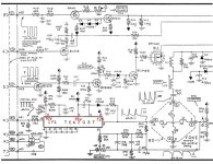
Ok, good progress, now the thing is to start with the schematic and write these voltages on it as we go, attached.

(it is more difficult without the scope, probes are cheap, but we can still probably get to the bottom of it)

The fact that the voltage is higher on pin 7 than pin 2 , tells us that the IC is basically operating, the flyback generator working, and likely there is AC deflection voltage at the IC's output pin but we need to check that.

For a test (sans the scope) you can use a common small speaker 4, 8 or 16 Ohms from a transistor radio or elsewhere. Put a 470 Ohm resistor in series with the speaker, connect it briefly between ground and the IC output pin 8 as an "audio probe". There should be a 60Hz buzz heard in the speaker if there is AC deflection voltage coming out of the IC's pin 8. If there is a buzz heard there:

Carefully look at the wiring from pin8, soldering and tracks and yoke connector (of there is one) Check the continuity of the vertical yoke coils on the Ohms range on the meter and connections back to capacitor CF3. And check yoke coupling capacitor CF3, if that was dried out and totally open, there would be negligible vertical deflection. If you don't have a capacitance tester & ESR meter, but have any electrolytic capacitor in the range of 100uF to 1000uF 16V or greater, temporarily connect it in parallel with CF3 (observe the correct polarity) and see if the vertical deflection appears on the screen.

If there was no buzz heard on the audio probe test on pin 8 of the IC (its output pin), then we go down a different road.
 

Attachments

  • Mac.jpg
    Mac.jpg
    198.9 KB · Views: 5
Last edited:
PS: if you don't have a speaker on hand you could use the one in the VDU, still put the 470R resistor in series, we don't want to feed to much energy to it, just enough to hear if there is a 60Hz signal on the output of the IC.
 
PS: if you don't have a speaker on hand you could use the one in the VDU, still put the 470R resistor in series, we don't want to feed to much energy to it, just enough to hear if there is a 60Hz signal on the output of the IC.
Im ordering probes for my scope because i need to learn how to use it and i need it for other projects, im a real noob with scope so i will watch videos to learn how to use it and maybe do you want the manual of the scope i will use, so maybe you can help me with it if i have problems ?
 
Im ordering probes for my scope because i need to learn how to use it and i need it for other projects, im a real noob with scope so i will watch videos to learn how to use it and maybe do you want the manual of the scope i will use, so maybe you can help me with it if i have problems ?
You should be ok with this job and practically any scope will work, because the frequency of the vertical scan waveform and other waveforms in this part of the circuit is low, at around 60 Hz (16.6mS period) and it is a very easy repetitive waveform for the scope to lock on to. Normally you would set the scope's sweep so that you can see a number of cycles of the wave, so if it was set for 10 or 20mS / cm would be fine. Use a x10 probe (which divides the input signal down by a factor of 10) but helps in two ways, it puts less load on what you are testing and it reduces the chance of accidentally feeding too much voltage into the scope's input. Then you adjust the scope's attenuator to get the height of the waveform about right on the screen, so then you can measure its amplitude on the vertical scale. Generally it pays to keep the scope on DC coupling, or you cannot see the DC axis or position of the waveform. However, if you are looking at a small AC signal, sitting on top of a large DC level (looking at noise on a power supply for one example) you have to use AC coupling, or the trace gets deflected far off screen by the DC.
 
Last edited:
You should be ok with this job and practically any scope will work, because the frequency of the vertical scan waveform and other waveforms in this part of the circuit is low, at around 60 Hz (16.6mS period) and it is a very easy repetitive waveform for the scope to lock on to. Normally you would set the scope's sweep so that you can see a number of cycles of the wave, so if it was set for 10 or 20mS / cm would be fine. Use a x10 probe (which divides the input signal down by a factor of 10) but helps in two ways, it puts less load on what you are testing and it reduces the chance of accidentally feeding too much voltage into the scope's input. Then you adjust the scope's attenuator to get the height of the waveform about right on the screen, so then you can measure its amplitude on the vertical scale. Generally it pays to keep the scope on DC coupling, or you cannot see the DC axis or position of the waveform. However, if you are looking at a small AC signal, sitting on top of a large DC level (looking at noise on a power supply for one example) you have to use AC coupling, or the trace gets deflected far off screen by the DC.
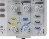
I just got my scope working, would you know a simple test to see if it's working or if the last owner maybe broke it messing around with it ?
 
What scope model is it ?

A lot of scopes have a little metal tab on the front on which a test signal is present, in this one, it has a 5V DC square wave test point in the bottom right of the case.

1702834330712.png

f it has one, connect the probe to that.
 
By looking at pictures of your scope, the calibration point is on the lower left below the screen. On some scopes it's a tab to hook the probe on to, on some it's a hole you can stick the probe in. While you're at it, you could also compensate your probe (while checking the test signal, adjust the trimmer in the probe so it shows the squarest wave)
 
Back
Top