With a signal of 2khz each wave should repeat every 0.0005 of a second, or 0.5 milliseconds.
With the CAL knob turned until it clicks at the CAL position and the main control set at .5 ms, each wave should fit in one horizontal graduation on the display
Its a 3V signal so with the outer knob clicked to 1 V/DIV it should, with CAL rotated until it clicks at the CAL position, should cover 3 graduations on the display. However some probes allow you to select X1 & X10 (or more) and this reduces the signal such that if set to X10, you will only fill 0.3 of a graduation rather than 3 of them
Play around with the AMPL controls & MAIN TB and see the effects
Things to note
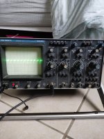
at the top of the scope you have three buttons and you have MAIN TB pushed in, this means the trace is controlled by the MAIN TB (TB means TIme Base) which is fine for now
on main time base control you have three more buttons AUTO TRIG SINGLE. These determine how the trace is Triggered or what causes the beam to scan across the screen. AUTO trigger is fine for now, but adjusting level may sometimes be necessary to get a stable trace.
At the bottom of this section, you have four buttons A B EXT MAINS. These select where the trigger (ie what starts the trace moving) comes from. Selected to A means the display is triggered from the signal you are currently measuring on input A. Selected to B would mean it would trigger the display on a signal on B (which might be useful if you wanted to see what was happening on input A, every time input B did something). EXT just means you can inject a third signal on the EXT connector, but you wont see it on the screen.
Lots more to discuss about scopes, but thats probably enough to be going on with
Please, ask questions
")
To me, a scope is the single most important tool this side of a screwdriver, but it is a tool and can tell you what you want to see if you dont use it and understand it.