• Please review our updated Terms and Rules here

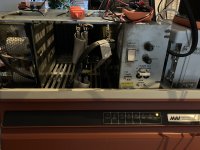
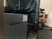
MAI 4101/310-01240

Right... RTFM time...
I can't find my exact machine, a 310, on bitsavers... but other models are available, which seem to share some of the components. The service manual for the 200/410 seems to allign quite nicely with the 310, the hard disk is different but the cardcage and power supply layout seems the same. Same goes for the operators manual for the 210. I need to dive into the parts- and/or board numbers to see how similar these are but on the face of it they seem the same.

And according to that manual the CPU boards need to be installed and the front panel in the door needs to be connected in order to start the CPU supply (which then turns the contactor on for the case fans and harddisk).
I would've liked to test the voltages on the CPU supply before connecting the actual CPU boards to it... but service manual first installs the cards and the ribbon cables, then checks the testpoints on the supplies.
 
I may need some advice on how to continue here... as I'm faced with a little chicken and egg problem. In order to test the CPU power supply I need to install the CPU boards (which also holds the ROMs to boot the system)... but I have no idea if the correct voltage will come out of said power supply, possibly damaging the CPU card and ROMs... for which I have not found a back up set to make new ones with.

I've thought about dumping the ROMs (N82S181N 8k PROM) but I can't find anything compatible in the software for the TL866 II and the website for the Chip tester Pro for example makes no mention of these PROM chips, or something compatible either. And I'm not really sure if just YOLO'ing a "figure it out" setting in such software could damage the ROM.
The pinout isn't that different from an AM27C16 by the way, although those have an extra adres line and a VPP line which the N82S181N lacks. Instead, it seems they've doubled up the 2 chip enable lines.
If these were common PC bios ROMs I would not really be this worried as a replacement can be found anywhere.

So, an idea that sprung to mind is to take the ROMs out of the CPU board and then use it to test the power supply. I don't think there is anything else on the boards that is special or unoptanium, and I also don't think the ROMs would be needed to start the power supply.

I could really use some feedback on this.
 
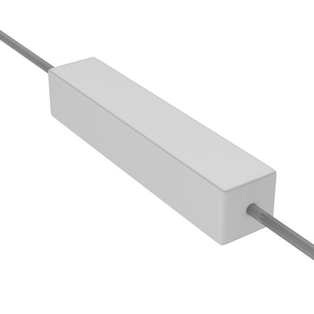
You could connect high power resistors to the power supply as a load and not risk your boards.

Select a resistance value equivalent to maybe 20% of the load. Connect just one set of resistors as a minimal load to see if the power supply is working at all. If so, start adding more resistors in parallel to increase the load on the power supply to see if it regulates correctly.
SQP10.jpg
 
You could connect high power resistors to the power supply as a load and not risk your boards.

Select a resistance value equivalent to maybe 20% of the load. Connect just one set of resistors as a minimal load to see if the power supply is working at all. If so, start adding more resistors in parallel to increase the load on the power supply to see if it regulates correctly.
Y
SQP10.jpg

You could connect high power resistors to the power supply as a load and not risk your boards.

Select a resistance value equivalent to maybe 20% of the load. Connect just one set of resistors as a minimal load to see if the power supply is working at all. If so, start adding more resistors in parallel to increase the load on the power supply to see if it regulates correctly.
SQP10.jpg
Yes, this would work with a normal supply.
In this case everything is slotted into a back plane using card edge connectors, including the 2 PSU's. And there are some interconnected lines between the 2, the 24V DC line from the distribution box runs to both the Memory and the CPU power supplies through the backplane, and also to the CPU cards... there is no "easy" way to isolate the main output of the CPU supply while keeping the control lines connected.
 
And there is something I don't really understand. Although there is a +24V going to the CPU PSU... I can't seem to find a ground for it, not a direct one at least, the lowest resistance I could find is around 25 ohms.
And the same goes for a 6V line that runs from the CPU PSU to the distribution side (right next to the Memory PSU) to power a contactor that turns the fans on and powers the harddisk. The ground side of this does not seem to be connected back to the CPU PSU... the colour choice of the wires of the distribution side is not helping either. I feel like I'm missing something really obvious... I think I need to draw a new schematic with some of the PSU boards connections in it.
I know nothing about this machine, but the strange situation that you describe sounds familiar. Does this machine have core memory?
The DEC PDP-8/L has a similar situation. In the 8/L, there is a MEMORY SUPPLY+ which is -6 volts, and a MEMORY SUPPLY- which is -30 volts. The drive circuits connect between MEMORY SUPPLY + and -, so for this to regulate there needs to be a load connected between those two outputs (no load to ground). It took me a while to figure this out, but looking at the schematic, particularly for the -6V MEMORY SUPPLY+ driver, that was the only way it could work, because the negative voltage output was built to source current.

I wonder in your situation if the +24V could be like memory supply+ and +6V could be like memory supply-?

In the PDP-8/L, the -6V regulator is super simple, 2 transistors and 2 resistors, plus a "base connection". It is designed to source current. How could a negative supply source current?!! Unless is is designed to output current through a load connected to a more negative supply.

It would be interesting to trace out the drive circuit for your +6V regulator. Maybe it's also a simple circuit with few components. Is it designed to sink current? Normally a +voltage regulator is designed to source current through a load connected to ground.

Anyway, I suspect this could be the reason for the rather strange lack of a return. The system might intend to have a load connected between +24V and +6V to regulate those outputs properly.

Please verify this by some other means before making the assumption, but it might be another avenue to explore.

Good luck! Sounds like a fun project!
Sadly, no core memory in this one... it's all just "boring" TTL stuff. I think this machine is a little to "new" (mid 80's) for core memory to be used (although I know some stuff did still use core memory in the 80's, my jukebox is a good example of that). But yeah, it sounds like a similary confusing setup. Although I think I have the mystery mostly solved.

I've been looking at various manuals on bitsavers from MAI machines that have a more or less similar layout. This cardcage seems to have been used in several systems from the same era.

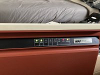
How I understand it now is that the Memory PSU is more of a backup supply, as in it keeps the contents of the RAM alive if it the machine is shut down. It charges the 12V battery and if the machine is turned off it keeps the memory boards powered on. It also powers part of the CPU boards that is needed to use the touch sensors on the front panel for turning the main power unit on and off.

The main confusion for me came from the way MAI labels everything in the computer. I was under the impression that the CPU supply is that, a supply for the CPU boards. But in the manual they call the entire cabinet the "CPU", which makes more sense with the actual layout of the machine. This CPU supply provides power for the entire backplane of the computer, including the RAM cards.

I get a feeling that the missing return runs through the CPU cards in some way. The reason I thought it was a +6V line was because it was connected to a 6V coil of a contactor that switches the 230V lines for the system fans and the harddisk. But this is connected to the 5V output of the CPU supply.

To play it safe, I've removed the ROMs from the CPU cards and installed them into the slots. Connected the front panel to both the CPU board and the CPU supply and turned it on.

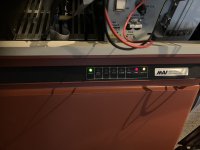
1LED.jpg

The "Reserve" LED comes on, this is exacly as the service manuals describe it. Under some of those LEDs is a little touch sensitve switch. If the one under the "Power" LED is touched...

3LED.jpg

Power comes on, and the machine ofcourse Halts right away as it has no ROM or RAM installed. But the large contactor for the system fan and harddisk actuates so the CPU supply is working now.

Now I need to become brave enough to install the ROMs back into the machine, add a RAM card and an I/O card and see if it wants to talk to the terminal.
 
After installing the ROMs back into the CPU card nothing really happened with the machine, apart from the fact I now have to press the "LOAD" button for the CPU to go into "RUN" mode.

There are some machine code diagnostic steps in the manual, but all they do for my machine is switch the CPU from "RUN" into "HALT" and the LED on 1 of the memory boards lights up (I have yet to figure out if that is a good or bad thing). I am not sure if those diagnostic steps even truly work on this machine as there are some differences between the description of my CPU cards and the one in the manual.

It also seems that the machine needs it's hard disk connected to really do anything, so going through that is next on the menu... and the power supply is up first.
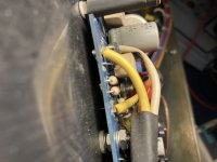
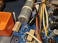
This looked fine at first, but I've noticed a burned wire that touched a power resistor and a 16V 1000uF cap that is bulging a bit. So it needs work.
 
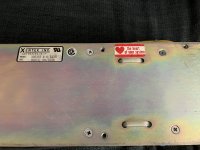
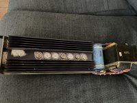
Everything else I could easily test looked fine, except the 1 bulging cap and burned wire. Some heat marks around some of the resistors, but nothing worrying as far as I could determine. Something I found really funny was this heart sticker on the baseplate of the supply, hidden behind a steel plate in the harddisk assembly. Well, this machines heart was not in good health...
HD-PSU1.jpg

HD-PSU2.jpg
The grey capacitor is the one that is bulging, and signs of leaking are visible. Instead of desoldering all the transistors on the heatsink from the PCB, I cut the bad cap off. This cap was truly dead, the inside was completly dry.
I did a bit of an ugly repair... in my defence, now the cap is no longer between 2 possibly hot power resistors so it should be happier there.

HD-PSU3.jpg

Again, I was not really willing to desolder the transistors that are mounted to the heatsink. That all has to be dismanteld before I can get to the underside of the board where all the solder connections are.

HD-PSU4.jpg

So, after that I plugged the supply into the testbench and it works pretty nicely. + and - 5V are bang on and the +24V is at 24,5V which is nice enough.

Just need to add some insulation to the white wire where it's burned.
 
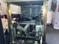
I've tried to put the machine mostly back together again and give it a quick test. The result is both promessing and disapointing (a little bit at least).
The good news is, the hard disk spins up and sounds alright. At lower RPM the bearing is a little noisy, but no horrible screach of a head that grinds the disksurface off.
The bad news, the machine just hangs and the disk did not become ready. I could press "Load" on the front panel and the heads will do a seek and very briefly show the disk ready LED but then quickly fall back into a Fault condition with the red LED on. If I then power the machine off via the front panel (but keeping the backup supply on) the RAM would show a parity error.

Today I noticed that the card that holds the processors and the ROM's is not connected to the backplanes data and adress busses, only to various power rails. All the data connections run through the CPU Accessory board and connect to the CPU board via 3 ribbon cables. So I've tested the whole setup without the CPU card, as the front panel connect the the CPU Accessory card aswell.

WIP.jpg

Now, the machine ofcourse does nothing other then turn on, it can't load anything or accept any commands because well... the CPU and ROMs are missing. But the hard disk does now show a green ready LED on the controller board of the hard disk unit. It also performed a seek test while starting up, something it doesn't do at start up when the CPU card is installed.

HD-ready.jpg

Now... I don't want to jump to conclussions to fast... but to me this sounds like the problem is with the CPU board... it feels to me that the proccessors connection to 1 of the busses in the system is borked somehow. If true... it would narrow the fault seeking to half a PCB instead of the whole system.
The downside is that I have not found this CPU in any of the documentation on bitsavers yet.
 
I was playing around with some jumper settings this morning on the both the CPU and the Memory Cards... and when I set the start of memory on 32K instead of 0K on the memory card... the disk ready LED on the front panel came on.
HD-ready-FP.jpg

When this happened I put the CPU into test mode and restarted the machine. When the disk ready light came up, I pressed load and...

Working.jpg

The test mode came up on the terminal, from here I could run the :CPU test program as described in the 200-410 manual and it started going through the various test options until it hit the printer test (which is not connected) and looped from there.

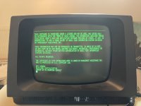
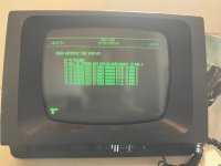
Excited as I was at this point, I shut the machine down again, set the CPU for normal operations and turned it back on. When the disk came ready and load was pressed the OS started to load. It gave an error that the first bank of memory was missing (which is correct as it was set to start at 32K) and then loaded into this screen.

Booting.jpg

When selecting an option here the hard drive made a sound that didn't sound to great (not a headcrash with the disk, but more as if the mechanism carrying the heads missed a beat or something) and that was the end of testing for now.
The disk ready light did not come on anymore, I'll have to look into that. Still, this was pretty exciting. (I have filmed the terminal while the machine was booting up... although this room is not made for filming so the quality is pretty poor...)
 
Left the machine to cool down for a bit, as there are a few components that run somewhat warm (which might contribute to instability). I've also set the memory back to start at 0 Kb.

The computer is working now, it fully loaded into Basic. The only thing I still need to test is if the second memory card can be used too, giving it it's full 256Kb of RAM again.

Ready.jpg

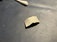
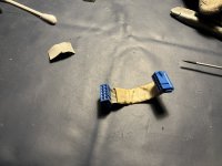
And I feel a little dumb now... because it's very likely that a little 10 pin ribbon cable was the sole reason it didn't want to work.

Argh.jpg
Ribbon.jpg

Even though this ribbon tested good with the multimeter. The machine never worked with this damaged bit in place (I had it wrapped in insulation tape). Now that this section is removed it suddenly started to work...

Next up, can it connect to multiple terminals, PC's with terminal emulators, my Osborne 1, a modern laptop?
I also need to dive into the Basic it uses.
And ofcourse I need to start going through that massive printer.
 
Last edited:
Fantastic! Seems like excellent progress.

Many problems are caused by something simple. But finding that simple thing can be quite difficult.
Yeah, I was grasping at straws already... looking at discolourations on chips to determine if they may or may not work anymore... The fact the little ribbon cable seemed to test good for continuity and didn't short to the other wire made me not fix it earlier. Just put some tape over it to prevent it shorting out.

Just curious, can you archive your Basic Four Disks? OR is there already a repository for BASIC FOUR software?
I don't know... I don't have any other disks then the fixed disk and that is more or less sealed like most PC hard disks are. This machine has no floppy as far as I know and I don't have the tape drive or tapes that go with it. Those tapes could be used to reinstall the OS but since this one doesn't seem to be protected I don't need to reinstall anything for the time being.
I also have not found any software online, just some of the manuals on Bitsavers.

I guess a back up can be made in some way using some programming and a modern PC with a terminal emulator on it, maybe, in theory... not something I would be able to do currently but an expert might be able to.
 
There is still some work to be done, the second memory board has a problem. It keeps giving parity errors. Not sure if this machine really needs a second memory card the way I'll use it (which is more of a showcase machine then the workhorse it used to be).
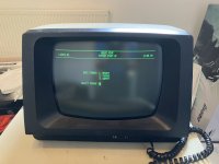
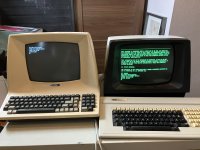
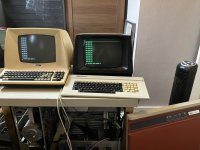
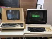
I have set it up with an additional terminal, a Televideo 910.

DuoTerm1.jpg

DuoTerm2.jpg

DuoTerm3.jpg

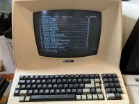
It seems that the termnial that is connected to connection 0 on the 8 way communication card is the Master terminal, it drops into Basic.

Adminstation.jpg

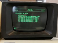
Connection T1 is not used, T2 - T7 seem to autostart some form of office program for business administration.

Workstation.jpg

I have made changed out a 25 pin serial plug for a 9 pin one, so it can be used to connect to a laptop/PC over USB.
 
The doubled o's and a's are dead giveaway. Could also be Flemish or possibly Afrikaans.

Just curious; what are you going to do with this thing?
 
Last edited:
Back
Top