• Please review our updated Terms and Rules here

MDA “clone” without crystal

jafir

Veteran Member
Joined
Aug 6, 2018
Messages
1,606
Location
Arkansas
So someone bumped a thread today where people were talking about the original MDA cards supporting color with a suitable monitor.


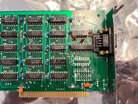
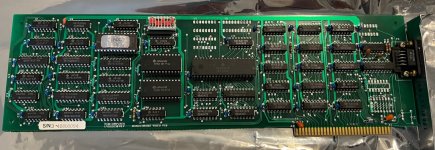
While I was reading it, there was a comment from Chuck wondering if there were any clones that supported that. I remember having a full length ISA monochrome card so I dug it out. It doesn’t seem to have connections on the rgb pins. And it turns out it’s not a clone, exactly, it doesn’t have a printer port, and the layout is completely different, using two 6116 chips instead of 8 2114. I do recall using it with the landmark supersoft diags, so it’s at least pretty close, functionally. And I think some software detected it as MDA not Hercules.

Anyway, I noticed that it doesn’t seem to have a crystal, unless I’m missing something. Isn’t a crystal required for MDA? Also it’s got a bunch of dip switches but without even a printer port, I cannot think of what they might configure. Anyone have any ideas?
 

Attachments

  • IMG_3722.jpeg
    IMG_3722.jpeg
    297.4 KB · Views: 42
Looks to me like a Taiwanese card made to keep the MDA cost low. Check pin B30--if there's connection, there's your clock. Font is probably 7x9 or some such. I suspect that this appears as a CGA card, but that's just a guess.

Maybe someone knows what system this belongs to.
 
I was thinking about the OSC signal at B30 as well. But MDA needs 16 MHz AFAIK. Otherwise you run into trouble when programming the 6845 video IC with values meant for a 16 MHz instead of 14+ MHz, I think. So I was thinking about a CGA equivalent of MDA. My question for @jafir: what monitor did you use? And the dipswitch settings?
 
I was using an old “samtron” MDA monitor. I wish I had an oscilloscope so I could measure the clk pin on the 6845. I guess maybe it’s time to finally invest in one.

I didn’t try any different switches on the video card, and I’m pretty sure I had the motherboard set for mono when I tried it. It was a turbo XT motherboard of some sort.

IMG_2568.jpeg
Ignore the geometry. That’s definitely the monitor and I haven’t opened it up yet. It does that no matter what is connected to it.
 
Well, if this is running from the OSC pin B30, we have a problem of sorts. Since this board's 6845 is initialized from the PC BIOS (i.e., there's no extension ROM on board) the sync frequencies have to be lower than a regular MDA's. The other possibility is that this is intended for use with a specific "Turbo" PC that simply outputs a 16MHz signal on B30, rather than the standard 14.3818MHz frequency. One might be able to get away with this if the display card and the motherboard were sold as a unit. It would save a couple of bucks in parts.
 
The other day I was looking at the docs for an ancient 6502 single-board computer called the JOLT (a TIM/RRIOT based system a lot like the KIM-1) that, presumably to save a couple bucks, used a free-running R/C network instead of a crystal oscillator to drive its 750khz-ish system clock. Would it be possible to bang up something like that which would stable enough to run at the around 16mhz of MDA?

I mean, I guess maybe we can’t completely rule out that this is running off the 14.3Mhz motherboard clock and just driving the monitor at, what, around 43hz? If that were the case, though, I’d think you’d have to mess with the monitor’s horizontal sizing controls?
 
Is it possible that they are taking it from the ISA bus, e.g. "If you move R25 to R11, then the 14.318MHz clock comes from the ISA bus. The motherboard's 14.318MHz oscillator isn't always accurate enough for CGA color composite video." from this cool looking board. Would that even work for MDA?
 
Modern FPGAs contain PLL circuitry which can synthesize a range of stable frequencies from a single input clock. I don't think MDA cards used PLLs, as it would likely be more expensive than simply using a crystal.

However, I know of at least one published hobbyist computer ("COMP JU+TER") which nominally used an 8000 kHz crystal for its CPU and video circuitry, and explicitly allowed for an RC option if no crystal was available. Although that system only did 13x8 characters on a TV, and I don't think this approach would be sufficient for MDA resolutions.
 
OP doesn’t have a scope…. yet! ;)

My multimeter seems to have a “hz” position for measuring frequency, but it seems to only go up to 999.99 kHz according to the manual.
 
OP doesn’t have a scope…. yet! ;)

My multimeter seems to have a “hz” position for measuring frequency, but it seems to only go up to 999.99 kHz according to the manual.

For laughs you could measure the frequency of pins 8 and 9 on the external connector; On a "proper" MDA with a 16.257MHz crystal the frequencies you should see on those pins would be around 18.4kHz and 50Hz respectively. If this card were doing something goofy like using the motherboard 14.3818MHz feed instead while still getting its CRTC programmed with the standard values those numbers would be around 16.2Khz and 44Hz respectively. (Again, though, I'd think in this situation even if your monitor synced up with it okay you'd probably have to twiddle a horizontal size pot on the monitor, otherwise the characters would probably go into the overscan on the sides.)
 
My original question was never answered as far as I can tell. "What's connected to bus pin B30?" If nothing, then there's a frequency source somewhere on that board.
 
So B30 appears to be connected, but it goes to unpopulated parts. It goes to a via which passes to the front side of the board near an unpopulated capacitor C5 (but I don’t think it is actually connected to either of those) and then there is a trace that runs up under the 9 pin connector to an unpopulated IC U10.

IMG_3738.jpeg
 

Attachments

  • IMG_3743.jpeg
    IMG_3743.jpeg
    511.1 KB · Views: 6
Ok. That’s it. I was wrong about B30. So the unpopulated U10 pin 8 was connected to B30 on the front side through all of that stuff I mentioned. On the back side pin 8 goes to pin 9 of U9 which is an HD74S04P, hex inverter. Pin 9 is the input to pin 8. Pin 8 goes to pin 7 of U3, which is an SN74LS166AN.
 
Back
Top