gwiley
Experienced Member
It seems like it’s converging. Made some updates based on comments, v2 review revision r04.
Changes since v2 r03:
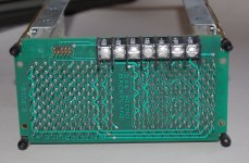
1. All power terminals are now on the top edge, or back of the backplane when mounted in a chassis.
2. Converted all power terminals to Keystone 1257 2-tab terminals. These are more like the terminals on the 8/M backplane. Keystone 1257 is available from Mouser and Digikey. This update supports 4 wire connections for +5V and 6 wire connections for GND, so systems can double or triple-up wires for +5V power. Single quick-connect terminals carrying high current are notorious for burning. My 8/M box has been modified to use 3 wires each for +5 and GND. Also, small debug systems using separate +5, +15 and -15 supplies can connect them directly to the backplane terminals.
3. Converted all mounting holes to use M3 cap screws. This way, fewer part types are required and less copper area is wasted around the mounting holes.
4. Related to Doug’s comment about fitting into an 8/E/F/M chassis, I realized the front of the backplane near the first slot also extended a bit too far forward if mounted in an 8/M chassis, so the front overhang was reduced by 4.5mm.
5. Added a single 0-ohm jumper to enable/disable the on-board Power OK circuit.
Images of the updated top and bottom layers of v2 review revision r04 are here:


A summary of the voltage drop on the +5V pins at each connector is in the following plot. Various combinations of the AWG 14 jumpers are shown. Installing only two jumpers is recommended: J7 to J8, and J11 to J12. Installing J9 to J10 provides almost no benefit so I might remove it from the layout. Moving the power terminals to the rear of the board and better layout has reduced the voltage drop compared to the previous version.

Changes since v2 r03:
1. All power terminals are now on the top edge, or back of the backplane when mounted in a chassis.
2. Converted all power terminals to Keystone 1257 2-tab terminals. These are more like the terminals on the 8/M backplane. Keystone 1257 is available from Mouser and Digikey. This update supports 4 wire connections for +5V and 6 wire connections for GND, so systems can double or triple-up wires for +5V power. Single quick-connect terminals carrying high current are notorious for burning. My 8/M box has been modified to use 3 wires each for +5 and GND. Also, small debug systems using separate +5, +15 and -15 supplies can connect them directly to the backplane terminals.
3. Converted all mounting holes to use M3 cap screws. This way, fewer part types are required and less copper area is wasted around the mounting holes.
4. Related to Doug’s comment about fitting into an 8/E/F/M chassis, I realized the front of the backplane near the first slot also extended a bit too far forward if mounted in an 8/M chassis, so the front overhang was reduced by 4.5mm.
5. Added a single 0-ohm jumper to enable/disable the on-board Power OK circuit.
Images of the updated top and bottom layers of v2 review revision r04 are here:
A summary of the voltage drop on the +5V pins at each connector is in the following plot. Various combinations of the AWG 14 jumpers are shown. Installing only two jumpers is recommended: J7 to J8, and J11 to J12. Installing J9 to J10 provides almost no benefit so I might remove it from the layout. Moving the power terminals to the rear of the board and better layout has reduced the voltage drop compared to the previous version.


")