• Please review our updated Terms and Rules here

Model I No Video

Don,
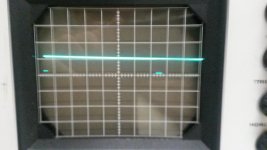
For the VDRV signal at C27-R44 the signal looks like it is correct. Also for HDRV C21-R43 the signal looks correct.

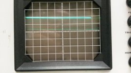
I'm thinking that you have a signal at Z5 Pin 5 & Z5 Pin 6, but that the O'scope isn't sync'd well enough to see it.
Try setting your scope for 1 or 2 volts per division, and sync off the scope probe channel you are using, and adjust
the level so you get a steady signal. You might have to change the horizontal sweep to a narrower sweep to see
several signals to get it to sync. If it is a quick & narrow pulse you may have to turn the brightness up a bit to see
the signal.

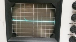
For the Z5 Pin 8 Photo, I'm thinking you need to turn the horizontal sweep down a lot to see a lot more of the sweep.
What you are seeing is a slow decay (dropping) across the area you are looking at. If you close up the signal, you
might see a true picture.

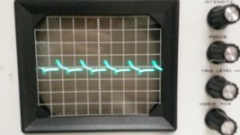
For the Z6 Pin Photo, Make your Volts per division smaller so you have a taller picture of the signal, and adjust the horizontal
sweep for several pulses, and adjust the sync level to get a steady picture.

Start at the C-27-R44 & C21-R43 junctions and work your way to the right until you get to Z5 Pin 8. I'm thinking you are real
close to the problem IC.

Larry
 
Larry,

I did manage to get better readings from Z5 pin 6 but could not manage any better readings from Z6 pin 8 than the ones I've already showed you.

Are we at a place where I can try troubleshooting by chip replacement... maybe Z6? I've already replaced Q1, Q2, and Z41 so what's a few more? :)

desertsagesolutions.com/attachments/Z5_pin_6.zip
 
Don,
I'm trying this post to see if I can post. I had to clear my cookies in Firefox for some reason.

Larry
 
I got a waveform from Z5 pin 11, but couldn't again from Z5 pin 8. So I replaced Z5. Now I get a waveform from Z5 pin 8 but not what I expected.
 

Attachments

  • Z5 pin 8.jpg
    Z5 pin 8.jpg
    91.6 KB · Views: 1
  • Z5 pin 11.jpg
    Z5 pin 11.jpg
    92.7 KB · Views: 1
Don,
Back up a bit to Z6 Pin 8 and check that signal is proper. (It should be a high going Pulse of 5 Volts with sweep around 10us).
Then chase that to Z5 Pin 13. If the signal is proper there, move to the output of Z5 Pin 11. Now there should be a 5 VDC
Low going Pulse with sweep around 10us.

Larry
 
Larry,

Z6 pin 8 is still a flat line at 5V. Same with Z5 pin 13. I tried everything to get better readings. I'm not sure why I can't.

I did get a waveform on Z5 pin 11 but it looks inverted.

Z5 pin 11a.jpgZ5 pin 11b.jpg
 
Don,
Back up to Z6 Pin 8 and see if you have the correct signal there. If not keep stepping backwards to Z6 Pin 10, until you have the correct
polarity signals. You may have one gate that isn't inverting the signal properly. You got to be close to finding it.

Larry
 
Larry,

Z6 pin 8 looks the same it has in previous tests. Here are the waveforms for Z6 pin 10 and Z6 pin 11. (it looks like the files attached pin 11 first, then 10)

Thanks!
 

Attachments

  • Z6 pin 10.jpg
    Z6 pin 10.jpg
    91.5 KB · Views: 1
  • Z6 pin 11.jpg
    Z6 pin 11.jpg
    90.7 KB · Views: 1
Don,
Yes, except your scope isn't in sync with the Low Going Pulse Signal for Z6 Pin 10. Try switching to MINUS for the sync choice of CH 1, and normal versus auto.
Then keep expanding your sweep as you adjust the level until you can capture two pulses on the o'scope display. You may have to also try auto. You should be able
to expand what you have and get a good picture, as it's there it's just out of sync.

You might have a bad gate right here or the next one that isn't inverting the pulse.


Larry
 
Last edited:
I have two more both set to minus, one auto, the other manual. I'm guessing when a low pulse is expected, change to minus. But when do you switch between auto and manual?

Thanks for being so gracious with your tutelage.


Z6 pin 10 minus auto.jpgZ6 pin 10 minus manual.jpg
 
Don,
OK, go forward one gate to Z6 Pin 8. It should be a Positive Going Pulse, Opposite of Z6 Pin 10. If that is correct step forward one more gate
to Z5 Pin 11.

http://www.hobbyprojects.com/oscilloscope_tutorial/oscilloscope_trigger_controls.html

In normal mode the oscilloscope only sweeps if the input signal reaches the set trigger point; otherwise (on an analog oscilloscope) the screen is blank
or (on a digital oscilloscope) frozen on the last acquired waveform. Normal mode can be disorienting since you may not see the signal at first if the
level control is not adjusted correctly.

Auto mode causes the oscilloscope to sweep, even without a trigger. If no signal is present, a timer in the oscilloscope triggers the sweep. This ensures
that the display will not disappear if the signal drops to small voltages. It is also the best mode to use if you are looking at many signals and do not want
to bother setting the trigger each time.

I had to look it up since it's been too long since I used my O'Scope.

Larry
 
SUCCESS!!!

I did get readings on Z6 pin 10 and Z5 pin 11 although not the expected ones. I still could not get readings on Z6 Pin 8. I decided to replace Z6 and thanks to FrankG I had the right chip on hand.

Now I get video! Again, not what I expected, but that's a huge win. Woot! I have the TRS-80 hooked to a TV though a modulator so it's not as clear as it should be but I think it tells the tale.


20160920_111828.jpg20160920_112026.jpg


More info: While troubleshooting the no video problem I replaced a homegrown character generator with a MCM6674P. Should I swap them back? It looked like the RS lowercase mod to me.

20160920_115719.jpg 20160920_115818.jpg

Even more info: Only letters seem to be affected. Numbers, arrows, semi colon, etc all work. So does everything on the numpad. Pressing shift has no effect. The cable between the keyboard and the cpu board is flaky to say the least.
 
Last edited:
Don,
Good! Now you can decode the MEM SIZE or MEMORY SIZE to the actual characters displayed and see what Bit(s) are changing
and decode that to the proper Video Ram IC(s).

You can replace the old flex cable with a ribbon cable and SIP headers.


Larry
 
Last edited:
SUCCESS!!!

I did get readings on Z6 pin 10 and Z5 pin 11 although not the expected ones. I still could not get readings on Z6 Pin 8. I decided to replace Z6 and thanks to FrankG I had the right chip on hand.

Now I get video! Again, not what I expected, but that's a huge win. Woot! I have the TRS-80 hooked to a TV though a modulator so it's not as clear as it should be but I think it tells the tale.


View attachment 33266View attachment 33265


More info: While troubleshooting the no video problem I replaced a homegrown character generator with a MCM6674P. Should I swap them back? It looked like the RS lowercase mod to me.

View attachment 33267 View attachment 33268

Even more info: Only letters seem to be affected. Numbers, arrows, semi colon, etc all work. So does everything on the numpad. Pressing shift has no effect. The cable between the keyboard and the cpu board is flaky to say the least.

I'd start looking at the ascii code and see if the characters you are supposed to get and the and the characters you actually get all have the same bit flipped. It may be a bad video RAM chip.
 
Is there a Synertek 21L02B equivalent? RT21L024 perhaps? Anyone know of a good source for the Model I video ram?
 
Don,
If you look closely you can see that your Model 1 is trying to put the PROPER Characters on the screen. The "MEMORY SIZE" characters are
placed accordingly, but due to some misplaced bits you are getting Graphics characters for some of the display. I used the actual MCM6670
Characters that Motorola published to decode a few of the characters.

The First Character should be "M" but shows up as LEFT ARROW. If you look at the attached file, you can see that the actual character being
displayed is in the first row, instead of being in the fourth row. Those bits are (A4..A6), so instead of being 100 you are getting 000.
000 1101 versus the proper 100 1101, so, Bit 6 is the wrong BIT.

The same is true for the "D" in RADIO SHACK where you are getting the Graphics Character instead of the "D".
000 0100 versus the proper 100 0100, so Bit 6 is the wrong Bit.


The same is true for the "Y" in MEMORY where you are getting the Right Arrow instead of the "Y".
000 1001 versus the Proper 101 1001, so here BOTH Bits 4 & 6 are wrong.

The MCM6670 Chart doesn't work for all your characters, and that tells me that your Character ROM has a
slightly different order from the original.

If you can read your EPROM into a HEX File, I can decode it, and get the exact Bit Patterns for each of the
128 Characters in the EPROM. I've done this for several different Character Generators. I've made an
Excel Spreadsheet of the ones I've worked on.

Larry

MCM6670-3.jpg
 
Try to get ahold of some video RAM. 21L02an or something equivalent. Once you have one start piggy backing the video ram one at a time till the display clears up. When it does clear you found the bad chip. So just replace it.
 
Back
Top