• Please review our updated Terms and Rules here

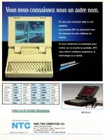
NanTan Early 1990's laptops Guide (386/486/Pentium)

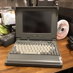
Extremely useful thread, though photos would help. Picked up an FMA8200 that arrived today; was intrigued by the extremely generic "Laptop Computer" sticker with no serial or model numbers, and the fact it was running NeXTSTEP of all things. Sadly the install for that is hosed, and the DOS 6.2 + Win 3.11 partition were incredibly bare bones, making for a terribly disappointing session of PC archaeology 😭. Config on mine is DX2 @ 66mhz + 300ish meg hard drive + 16mb of RAM. Definitely respectable.

Not really sure what to do with it, however. The lack of sound could be remedied via the PC Card slots I am sure, but it's also sadly held back by being the passive matrix color screen variant, and a keyboard that isn't really good enough to turn it into a distraction-free writing machine.

Don't suppose anyone knows of an active matrix that could be easily swapped in?
 

Attachments

  • Photo Oct 09 2024, 04 18 49.jpg
    Photo Oct 09 2024, 04 18 49.jpg
    1.2 MB · Views: 11
Unfortunately with this era of laptop, every display type (and sometimes even display vendor) used a different cable. That means you'll need some unobtanium cable in order to install an active matrix panel.
The Nan Tan 8200 definitely did ship with TFT displays, but those models are very rare. I haven't yet seen a photo of one.
I have a somewhat complete specsheet up on my website: https://macdat.net/pc/nantan/fma8200_home.html
 
Figured as much, but one can always hope, huh? I was actually looking at your site earlier for reference, heh. Great resource.
 
I'm glad it was useful to you :)
One with a TFT screen will show up eventually, they always do. I'm sure you'll be able to get your hands on one (if I don't buy it first)
 
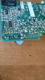
Calling anyone who has an FMA3300 (or knows electronics on a lower level in general). @GiGaBiTe , you seem to be particularily knowledgeable on this sort of stuff. I've got a problem: about 8 months ago I was replacing some capacitors on the power supply board, and accidentally connected the wrong wire to the + of the below capacitor C2 (the one with the green jumper wire going from it - I connected it back where it should be, on the - terminal, but the damage was done once I first powered on without realizing my mistake):
IMG20241121105017.jpg
After fixing the connection and replacing that capacitor since it could have gotten damaged, all I'm now getting is the board constantly powering on and immediately off again, over and over. Definitely a short somewhere.

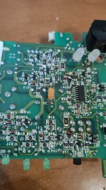
The first component that died was a TL494C: it blew up from from its bottom, and I replaced it with a new one. Still, same issue. I had many other things to do and only now got around to searching for the 2nd problem. And I thought I found it with the one tantalum on the entire board being shorted, but removing it revealed that it's not the capacitor but the board that's shorted, only at the two connections where the capacitor is:

IMG20241121105116.jpg

Only 2 SMD ICs left, an LM339 and LM555CM, both of which appear to be unaffected. There's 2 IRFZ44 MOSFETs, and on the first one's the S pin doesn't have continuity with ground, but on the other's it does. Failure on the other one perhaps? Also there's a TIC126M whose K pin is connected to ground.

Another thing I'm interested in is if there's a way to reliably test components on-board. I've heard that with resistors this could get quite tricky, but I'm not sure if that's the case for other components as well. My wording of electronics-related questions get Google quite confused sometimes, and I figure it's better to ask real people anyway.
 
Was that board attacked with a bernzomatic torch? It has burn marks all over.

C33 looks burned and potentially cracked. A capacitor leg its attached to is bent over at a 90 degree angle and looks like its almost shorting on R64. Another leg, presumably from the same part on the other side of the board has a cooked VIA with a leg also bent at a 90 degree angle going to maybe Q20?

U4 is not soldered to the board properly and is floating. Half of the pins don't even look attached properly. There's what appears to be a solder blob under the top of the chip that's possibly shorting to a VIA.

There's yellow glue on the green wire. That stuff becomes conductive over time, it needs to be removed.

The connector next to TP3 has a corroded/burned pin that needs to be fixed. Below the pin, there's a random blob of solder hanging off the edge of a solder joint that looks like it'll fall off.

For the reverse power event, quite literally anything could be damaged that was connected to wherever the power was. If you had the board plugged into something else, that could have killed lots of stuff there as well. You'll need to trace both upstream and downstream of the reverse power and start checking everything, including passives. MLCC caps, diodes, resistors, transistors, mosfets, etc. If there's a buck/boost circuit there, you may have blown up the PWM driver as well as the mosfets.
 
I probably wouldn't have noticed half of the things you mentioned here, most of them my dumb faults. I think I should play around with some scrap boards first, because if I touch it at this point there's a good chance I'll find a way to create another problem. Anyway, thanks for taking your time to look at this mess I've made!
 
A capacitor does look burnt, it's much darker than the color of other cap's in the area. There's also a couple of very long leads to the right of U4 in the second photo too. They should be trimmed back so they don't short to some other traces or components while you work on the board. I would say that you need more heat in your soldering iron's tip and maybe more flux. Good solder wick does wonder in removing old solder so you don't end up with a large lump of solder that requires a lot of heat. Plus an old toothbrush and 90 to 99% isopropyl alcohol cleans up the new soldering, removing left over flux, so you can see if the solder has bridged to the wrong place. Also, take pictures before you remove components so you can make sure to not solder to the wrong place. Good luck with your repairs.
 
I would guess too much heat was used over too long a period of time, that solder flux is almost black.

As you said, the iron needs more heat and/or the tip be cleaned more regularly to avoid having to keep the iron in one place too long. This looks like my soldering 25 years ago when I was in middle school. I had a crappy Radioshack iron that was only 25W and no flux besides the stuff already in the solder wire lol.

I'd recommend getting a few syringes of non-rosin flux that doesn't burn as easily. Also a good soldering iron with a variety of tips and a hot air station for SMD stuff.
I don't think I held the iron(s) on for too long when removing the old tantalum, it took literally less than 2 seconds for the solder to melt w/o any flux, but I added some anyway to help things flow. Both of them were set at 350 degC (well, one was anyway, the other is +-10% of that). Just today I replaced the SMD eject button on a CD-ROM drive and after cleaning everything up with IPA it looked like I'd never even messed with it, so I think I was just being messy with that board and haven't cleaned anything up. I do have a T942-something soldering iron made by Quicko, ordered from AliExpress some 5 months ago. Also got a couple of original Hakko tips for it, the ones that came with it were untinnable! Before that I had some $5 thing I can barely call an iron, that thing was literally melting PCBs. So I've got OK equipment I'd say, except for maybe the flux. I think practice is what I need most of all really.
A capacitor does look burnt, it's much darker than the color of other cap's in the area. There's also a couple of very long leads to the right of U4 in the second photo too. They should be trimmed back so they don't short to some other traces or components while you work on the board. I would say that you need more heat in your soldering iron's tip and maybe more flux. Good solder wick does wonder in removing old solder so you don't end up with a large lump of solder that requires a lot of heat. Plus an old toothbrush and 90 to 99% isopropyl alcohol cleans up the new soldering, removing left over flux, so you can see if the solder has bridged to the wrong place. Also, take pictures before you remove components so you can make sure to not solder to the wrong place. Good luck with your repairs.
Yeah I think I burnt it since I powered the board with the short still present lol. Those long leads are the result of me simply being lazy and getting demotivated the 1st time attempting to repair this board when it didn't turn out how I'd planned. I removed them just after taking photos and uploading them here, and before that they (thankfully) weren't shorting anything. Also you know what's funny? I did take pictures of all components before doing anything _at all_. I uploaded them here, they're a couple of pages back. I guess I wasn't really thinking about what I was doing when replacing that capacitor. That's a way to make sure such a mistake never happens again. BTW, about solder wick: that stuff never worked for me for removing solder from holes. Don't know how: I put new solder. I put flux. I tried doing it from both sides. But there's always some that stays in. It is useful for cleaning pads, but that's about all I use it for.

Thanks to both of you for giving me advice, I really appreciate it! I'll do a bit more "work" on junk boards first, and only then come back to this one since I'm a bit afraid of screwing things up *completely* beyond repair.
 
Back
Top