DDS
Veteran Member
I've been following this thread hoping to see some solid resolution of something that a common collector can do with rusty cases, but so far it has been all over the place.
So, yes, the ideal solution is to take it to a professional, and have them blast/repowder it. Perhaps a few people here have that kind of equipment, know other that do it, or have piles of money, but not most.
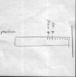
So what exactly should a common person do within reason? (things one can get at Home Repo, etc)
I would hope that some commonly available rust remover, plus some kind of spray paint would be a serviceable solution? At least one that would improve the appearance, and halt rust? Would any of this prevent a professional form re-doing it later?
Firstly, forget removing the rust without damaging the existing paint. Metallic oxides are pretty tough. That's why we use them to make sandpaper. Second, plan on any rust you merely cover up coming back at some point.
Sooooo.
Do whatever you like. Its your computer. But if you want it to look right after you do it, and still look right six months after that, you're going to need to (one more time):
1. Soda blast. The only step that most folks probably can't do at home. Or sand it. Time vs. Money. vs. Elbow Grease. You get to choose. Use a grit size that won't leave huge scratches in the steel. Your primer and top coat may or may not flow out enough to fill them.
2. Neutralize. The shop that does step 1 can do this for you. If you sanded the rust off you won't have anything to neutralize. Just wipe it down with a tack rag.
3. Prime with a good primer compatible with step 4.
4. Top coat with a good paint compatible with step 3.
Steps 2 - 4 can be done at home with any weak acid, lemon juice, household vinegar, whatever, and rattle cans from your favorite hardware store. Be advised that as soon as the steel surface is exposed to atmospheric oxygen and humidity it will begin to oxidize. This is one of the best reasons to have it all done at a shop that has the materials and equipment to do it right. Again, your computer, your wallet, your shortcuts, your results.
But if it looks like "heck" in 6 months you might be questioning why you didn't do it right in the first place. And remember that 90% of a good looking paint job, on your house, your car, or your computer, is a direct result of proper surface prep.
One more tip. If you really really care how it comes out, practice with your selected technique on some scrap metal before you risk boogering up your "soon to be beautiful" computer case. Maybe practice several approaches and different materials and see what comes out best for you.
Good luck!
Last edited:
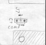
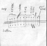
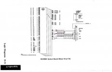
") I have been able to figure out that the thing connects to a +5VDC trace from the PSU, but I got confused and thought this had something to do with the keyboard; thanks for pointing out that it's actually just cassette-port related. Could you elaborate on what this thing actually does?
I have been able to figure out that the thing connects to a +5VDC trace from the PSU, but I got confused and thought this had something to do with the keyboard; thanks for pointing out that it's actually just cassette-port related. Could you elaborate on what this thing actually does?