• Please review our updated Terms and Rules here

Need help with Osborne executive

kpug

Member
Joined
May 7, 2024
Messages
38
currently working on an Osborne executive computer, I am relatively experienced with electronics in general, not so much with older computers such as this.
When we got it, we noticed all the RIFA caps on the psu had blown, going to completely recap the board soon. Until then, I have hooked the machine up to two separate bench psu's. The best result I have gotten so far is a blank orange screen yesterday. Today I turned it on and received the same blank orange screen for a few minutes when the screen went out completely.
So far, I have checked the crt, which seems fine. and attempted to read the voltage coming off of the internal monitor rail, however It does not seem to be outputting +12v
with the bench psu's If I turn on the machine providing +5V the external video will register to my tv (that is to say it goes to a black screen instead of a "no input") and the amperage reads within range. However, when I turn on the +12v PSU It displays no amperage being pulled which was the same before, where it would read 12v 0A if the monitor was not plugged in.

If I am reading the voltage out from the internal monitor connector right, I get ~4.5 volts out on what should be the +12V rail.
However I am unsure if I am reading it correctly as the layout of the connector does not seem to line up with that of the one in the circuit diagram.

Any help would be greatly appreciated.
Thanks
 
Update, turns out the probes from the PSU giving +12V somehow got cooked (they were very old and scuffed so not too surprising).

Replacing them got the crt back up and we now have this (see image) a blank orange screen.

I have seen the manual, been lurking almost every mention of Osborne executive or 1 on the internet for a while and finally decided to ask for some help myself.
I have accumulated the service manual, a German manual for the 7" zenith display and Osborne executive from a now defunct website mentioned on another thread on this website (used way back machine to acquire them) and one or two other mostly the same PDFs.

So far, I have gone through and checked that all resistors in the display are still good, they are.
We know the og PSU is dead as all of the rifa caps were blown.

Otherwise I have not done much, messed with the display settings (both the ones on the front and inside the crt assembly)

Any other ideas would be greatly appreciated
 
Here is the current status of the crt, apologies, forgot to attach on previous post
 

Attachments

  • 20240507_152741.mp4
    2.8 MB
Quick question, and sorry if its stupid.
On every photo or video of the Osborne executive logic board there is are a few little blue cables running between the chips.
Is this only on certain models?
My one only had 1 of said blue cable when I opened it. I am not sure of it's history.
 
>>> I had to do exactly the same thing with the original design documents for the Sputnik 1 Satellite, that were in Russian.

Is this your next re-creation project Hugo?!

Back to the Osborne...

I assume you have the 'plug' installed to use the internal monitor? This is in the section marked "EXT VIDEO" on the lower right of the front panel.

You appear to have a full raster on the screen.

I would next check the H SYNC, V SYNC and VIDEO signals with an oscilloscope between the logic board and the monitor to see whether or not we have sensible signals. What we are hoping to do is to identify whether it is the logic board, the monitor, or a combination of the two that is/are faulty.

I am assuming you do have an oscillosope?

Dave
 
If by "plug" you mean the little black box labelled "do not remove while power is on" which allows for video, yes. If I remember correctly, if that is not plugged in the monitor will not receive +12v to display anything.
As far as the oscilloscope goes, I am working on procuring one as we speak, if/when I am able to find one, what should I be looking for?
I will send a picture of the whole setup soon.

two notes however:
1. will the computer still boot if the floppy drives are not plugged in? I can plug them in, just don't have them wired up to the bench psu yet.
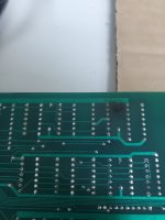
2. there is a black dot that looks a little "burny" on the back of the (I think its the ram board, the one that sits on top of the logic board and uses the large pinset on the far right. I will send a pic soon, it looks a little extravagant for a small ram chip, and the chip it is below has no visual deformation.
 
Currently working on locating an oscilloscope, but may be a little while, apologies.
Is there any other checks I can do? I can plug the board into an external monitor if that would help.

Also, just a general question about oscilloscopes: other than creature comforts, have they changed much between vintage or just older models and newer ones? I am on a fairly tight budget so I was thinking I might be able to find an old one for cheap.
 
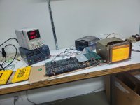
Here are some photos of the current setup, added the floppy disks rather quickly so will have to double check their wiring.
The drives do not light up when I turn on both PSU's, but I noticed a slight hum when the +5V supply was off and the +12V supply was on, (accidentally did this and noticed what sounds like motor hum. In addition, one of the photos is of the back of the ram board ( I think) with that mark I mentioned earlier.

here is a photo of the setup powered on after I attached the floppy disk drives: (cardboard is for insulation :p) (please excuse the mess)
20240508_100937.jpg

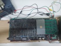
here is a photo of the logic board: (I took this before redoing the wiring to add the drives, hence the change in wiring between these photos)
1715174491838.jpeg

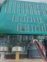
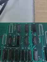
here is the back of the ram board with the black dot: (I can send more photos later if there is something yall might want to see)
1715174688683.jpeg
 
>>> If by "plug" you mean the little black box labelled "do not remove while power is on" which allows for video, yes.

That's the thing... I thought it was there, but I thought I would double check... They have a habbit of 'separating' from their computer. You are correct about the monitor supply though.

You are still under moderation, so your posts are appearing sporadically. You will inevitably require an oscilloscope to diagnose video faults, unless you are lucky...

Burnt sections need to be investigated BEFORE powering up anything.

There are some good second-hand oscilloscopes on the market. I will post something later on the matter.

Dave
 
I just checked the burnt section, it's under what looks like a resistor, Labelled C1. I was unable to locate it on the schematic, but I did check the resistance in comparison to the other identical resistors next to it and they all read the same. I believe the reading was 4.88 kohms. But will check again when I get the chance
 
C1 is a capacitor, not a resistor. Probably a decoupling capacitor.

If this is true, you are not reading the resistance of the capacitor (if that makes sense) but of the logic chips and power supply etc.

Can you post a photograph of the dead component and a good-looking device of what looks to be the same type.

Dave
 
20240508_131840.jpg
Attached are photos of the back and front of the ram board, with capacitor C1 and C2
20240508_131846.jpg
 
My main oscilloscope is a Hitachi V-509. A very nice (light and portable) 2-channel analogue oscilloscope with a delay on the timebase.

Of course, these are now obsolete, but other models are available...

Avoid the cheap things that are being sold though - the user interface is rubbish and the specifications are not as good as they make out! False economy...

Dave
 
alright, thank you.
I am attempting to get a reading of the capacitance but it is proving to be a little tricky.
I will continue and update with any findings, thank you for the help thus far.
Any ideas of what the capacitance should be?

I keep getting different readings for the capacitance of C2 and C1, to get any reading I have to get the probes positioned very precisely.
any ideas on what I might be doing wrong?
will update If I get any concrete findings
 
I am just guessing without either a photograph of the part - or finding it on the schematic or parts list!

I will have a look at the schematic tomorrow morning.

Dave
 
OK...
I de-soldered both C1 and C2.
They are both labelled 60V, (A symbol that looks like a C, though it might be a sideways n to signify nano farads), 104

both read 104 nano farads, for C2 interestingly I had to read twice to get 104, initially it only read 98 and slowly worked up to 104. Re doing the measurements 3 times confirmed 104 nano farads on both caps, the funkyness with the initial reading of C2 only happened the first time, every other time they both immediately read 104 nF.
 
104 actually means 100,000 pF = 100 nF = 0.1 uF.

These are clearly power supply decoupling capacitors.

Capacitors have a fairly wide tolerance, so 98 nF is so close to 100 nF that it wouldn't bother me.

It would be strange for a decoupling capacitor (assuming it is ceramic) to overheat as it did though. These things are pretty robust.

Dave
 
Back
Top