• Please review our updated Terms and Rules here

Neglected PET needing some love

Divarin

Veteran Member
Joined
Mar 9, 2019
Messages
565
Location
Cleveland, OH
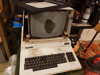
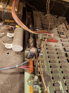
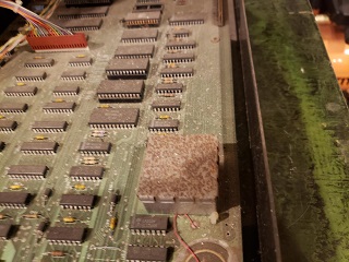
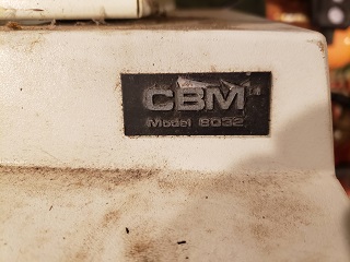
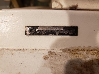
I picked up this badly neglected Commodore PET for $50. I'm looking to restore it.

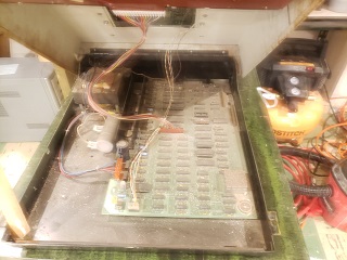
So far I haven't done anything with it, my plan is to first test the power supply and fix it if necessary, then find some way to get video out so I can start to examine the computer itself, see if it works, and fix as needed.

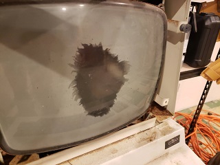
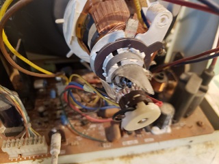
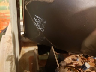
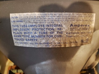
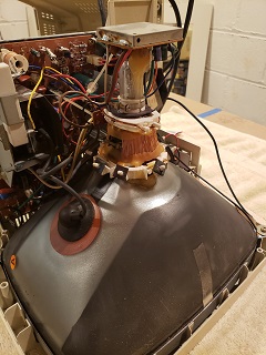
The first thing you notice is the monitor is completely shot and will need to be replaced. I have two questions (for now I'm sure I'll have may more later):

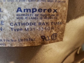
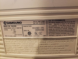
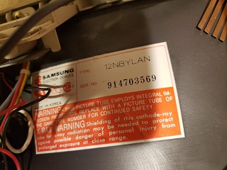
1) What CRT's could be used in this thing? I do have an amber CRT monitor (monochrome text-only) which works I thought it might be nice to put that in the PET. It would be unusual having a PET with an amber monitor, They appear to be the same size (12") but otherwise I have no idea if the amber CRT would be compatible or not.

2) Is there any way to get video out to something else, even if just temporarily for testing the computer such as composite or anything else?

I don't have much experience working with CRTs and have never attempted swapping them. I know about the high voltage and the importance of discharging it before attempting any work but as for anything else involved this is all new territory for me so any guidance is greatly appreciated.

th_20220912_092830.jpg
Full Size Image
th_20220912_092834.jpg
Full Size Image
th_20220912_092836.jpg
Full Size Image
th_20220912_092940.jpg
Full Size Image
th_20220912_092946.jpg
Full Size Image
th_20220912_092954.jpg
Full Size Image
th_20220912_093016.jpg
Full Size Image
th_20220912_093025.jpg
Full Size Image
th_20220912_093029.jpg
Full Size Image

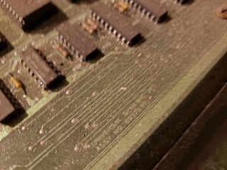
p.s. my apologies for the blurry photos. If there's any part in particular you need a better photo of let me know. Thanks.
 
It is possible to take the V-Drive, H-Drive and Video-Out signals from a PET and combine them using a relatively simple circuit to make Composite-Video out. This is discussed at some length in this older thread on the subject:-


You could perhaps find a small Monochrome CCTV monitor and install the complete works (PCB + Tube) inside the monitor housing of the PET, using one of the above simple interfaces as the 'bridge' between the separate outputs from the PET and the single composite-in of the CCTV monitor. Of course most CCTV monitors have white phospor, so that might not appeal to you.
 
  • Like
Reactions: ACK
It needs love for sure but nothing to bad really. Going to need a sand and paint but it will look like new when done. Sirius Hardware is correct about making the Composite out. IF you dont have the chops you can buy an already made video out module from Tynemouth Software. I think your most difficult hurdle will be sourcing a compatible CRT tube.. And I would go for whatever works whether its B&W, Green, or Amber If it was mine that is.
 
  • Like
Reactions: ACK
Let us know what manufacturer and part number for the tube(s) you have is/are and we should be able to look them up and see if they stand a chance of being compatible with the monitor circuitry.

Dave
 
  • Like
Reactions: ACK
okay that sounds promising. I'll have to dig in further and get more details about this model specially but if i can get composite out (even if they ends up only working on a crt) then I'm in luck.

I'm leaving for vacation tomorrow so I won't have time to look closer until I get back but it sounds like there's some options.
 
Provided the neck diameter and deflection angle is the same and the screen size & mountings are compatible, monochrome CRT's of this size are very interchangeable and their EHT voltages and gun voltages are very close. Most (not all ) use a 12V heater. The gun wiring can be figured out by looking at the base of the CRT, which electrodes the pins connect to, this is not standard and the socket might need wires swapped around. Generally most guns have a standard configuration. I could help you fit your Amber CRT.

If you get the type number of the CRT, Newtubes on Ebay have large stocks of CRT's and an equivalence list, most likely they will send you a compatible part. Richardson Electronics in the USA also have good CRT stocks and may well stock the original 12" part. They stocked the 9" PET CRT's but I bought the last of those.

A tube let down to air as yours is, what happens when the exhaust tip or neck is snapped off, air rushes at high speed into the tube and strikes the aluminized phosphor, dislodging it from the faceplate, so it falls off in a round or oval zone in the screen center.

Since there is air in your tube, it is now not possible for the tube to store any charge. Also, don't power the VDU like this, as the final anode will arc over in the gun assembly and that is bad for the circuitry, video amp and EHT generating system.

(Unfortunately, there is nobody in the world currently who offer a service to re-screen and re-gun your CRT. The last company that could do it, in France, closed down over 10 years ago CRT's are now a "non-renewable resource").

You don't have to discharge a CRT while working on a de-powered VDU, provided you do not go under the insulated EHT (anode cap).

In the CRT the stored charge is isolated and after switch off and you cannot contact that charge unless you go under the anode cap and touch the CRT's final anode connection.

The charge is also totally isolated from the tube base pins (if it were not the charge would quickly bleed away out those into the gun support circuitry and not be "stored").

In VDU's though, after turn off the CRT's final anode charge slowly dissipates on its own, because the EHT rectifier has non zero leakage.

If I want to go under or remove the EHT cap, I just leave the set off for a day.

Even in cases where the CRT is not discharged and one goes under the anode cap in short order, after turning the sett of, the zap from it has an equivalent energy (for CRT's in this size range) to a single hit from a lawn mover or car spark plug connection, it is generally less than 100mJ to 200mJ. Though I wouldn't recommend it as it is unpleasant. If you withdraw your hand with the zap you could break something or gash your skin on metalwork. Also a large color TV CRT can store up to a Joule or two of energy. Farmer's electric fences generally go to around 8J or more and that is a very significant hit, but even that doesn't kill humans or cattle very often.

The main reason to discharge a CRT is to remove it from the set and carry it across a room. If there is some charge stored in the bulb and the hand brushes over the anode connection, you can drop the CRT on the floor because of the muscle twitch.

Discharging CRT's is more about safety for the CRT than the technician, but some people get carried away about the whole idea, probably because they did not know that the stored charge is isolated from the CRT's base pins and you can work on the turned off VDU as much as you want, if you don't go under the anode cap. Generally for most servicing there is no need to go under there, except perhaps with the set running and you want to measure the EHT with an EHT probe. Though, often the EHT measurement itself is not required, one reason being that the size raster scan you see on the VDU is inversely proportional to the square root of the EHT voltage. So if that is about right, size wise (and nobody has tampered with the height and width controls) then the EHT must be close to correct in value.

If you do feel compelled to discharge the CRT, the EHT probe is a very good way to do it, these contain a very high voltage rated resistor, usually 1Gohm or more and give a nice gentle current limited discharge, rather than shorting the anode out with a link wire which creates very high initial peak currents. As a general principle, if you want to discharge any type of charged capacitor, rather than shorting it out directly, it is much better to do it via a suitable resistance which limits the peak current.
 
Last edited:
...PS: in these 12" PET VDU's there are 400V potentials at a few circuit points, so you need to be cautious of those, when working on the powered VDU.
 
  • Like
Reactions: ACK
Wow that's a lot of good info, thanks.

When I get back from vacation I'll start pulling this computer/monitor apart and post some pics so we can determine if the amber screen will work or if not then what other CRTs might work instead.

I'm pretty excited about getting some sort of composite output not only to be able to test the computer itself but also that would ensure that some sort of monitor could be fitted even if I can't source a direct, drop-in replacement CRT.
 
  • Like
Reactions: ACK
  • Like
Reactions: ACK
How exactly did the neck get smashed as its inside the CRT enclosure. Did the front 4 mounting points on the imposion band break off?
 
  • Like
Reactions: ACK
What a shame about that lovely Amperex CRT. As I mentioned, a neck fracture results in the acoustic blast that blew the phosphor off the screen, very sad.

From what I can tell, the neck diameter and the deflection angle and mounting tabs look similar on the two CRT's.

Assuming you cannot get the original CRT:

The options are to fit the Amber CRT tube only to the PET VDU's circuitry, that would keep things as original as possible.

Or, leave the Amber CRT and its pcb assembly together as it is probably working, and fit that to the PET VDU housing and use the adapter circuit to create the composite video it requires from the PET's 3 signals.

To adapt the CRT into the PET electronics, would require (to make it easier ) the schematic for the Amber VDU, to compare the CRT's base diagrams in the PET's VDU and check if the wiring is the same, likely different. So the Gun can be correctly wired and the focus voltages & heater voltages compared and modified if required. But, if the Amber VDU schematic is not available, inspection of the gun connections and a test of the heater voltage can be done.

EDIT: I just looked up that Amber VDU...apparently it is a TTL MDA monitor with an H scan rate of 18.4Khz and not a composite VDU. So it looks like the CRT substitution might be the way to go. The CRT is said to have a flat and black non glare screen (sounds good) but if it is too flat its might not fit the original PET escutcheon. Does its faceplate radius of curvature look similar to the Amperex tube ? Is the neck diameter the same ?

Can you post the link to the exact schematic of your PET VDU ?
 
Last edited:
  • Like
Reactions: ACK
An Amber CRT.. now that would be an attractive machine.
Yes, there is something about the Amber phosphor, it is my favorite for a monochrome computer VDU, followed by green, followed by white. But white is good if there are photographic images rather than just symbols or text, so its a hard call.

Also , despite the fact that many "green CRT's" are said to have the P31 phosphor, or the designation GH, there are a number of grades of this in practice with the color of the green and the persistence of it. The Amperex CRT's used in Green PETs, have a very pleasant green and short to medium persistence. I bought an equivalent to the green CRT in the PET, said to be P31, but the persistence is much longer leaving comet tails behind moving "graphics". So it was not the same as the Amperex -GH suffix CRT. Also those Amperex CRT's, are "special" in that they are an "industrial" not a domestic quality TV CRT. They have a much more robust electron gun structure with a substantially larger cathode assembly and they have a very fine pitched focused spot, better than most TV CRT's of the same size.
 
  • Like
Reactions: ACK
I'll take a close look at the VDU today and try to see if I can find schematics for it. I spent yesterday just completely disassembling the computer so that everything can be cleaned and the chassis sanded (to get rid of the rust) and painted.
 
  • Like
Reactions: ACK
I'll take a close look at the VDU today and try to see if I can find schematics for it. I spent yesterday just completely disassembling the computer so that everything can be cleaned and the chassis sanded (to get rid of the rust) and painted.
If you are painting over an area where there were rust spots, regardless of the preparation with various grade papers, it is worth treating the rusted areas with Fertan organic rust converter. If you don't, the rust will reappear at a later date under the new paint. The Fertan converts the rust crystals into a harmless blue-black colored organic compound. There is often more rust than there appears on face value inspection. The Fertan though finds & reacts with it. There are some notes about this in this article on restoring a PET VDU:

 
  • Like
Reactions: ACK
If you are painting over an area where there were rust spots, regardless of the preparation with various grade papers, it is worth treating the rusted areas with Fertan organic rust converter. If you don't, the rust will reappear at a later date under the new paint. The Fertan converts the rust crystals into a harmless blue-black colored organic compound. There is often more rust than there appears on face value inspection. The Fertan though finds & reacts with it. There are some notes about this in this article on restoring a PET VDU:

That's a good idea I'll do that. I think I could use some of that on my cars rusting away in the driveway :)
 
  • Like
Reactions: ACK
unfortunatly I'm unable to find a schematic for the VDU.

I'm also not able to determine the correct heater voltage (or any details really) about either the pet's original monitor (type M31-334GH) or the one I'd like to fit in its place (12NBYLAN)
 
Last edited:
  • Like
Reactions: ACK
unfortunatly I'm unable to find a schematic for the VDU.

I'm also not able to determine the correct heater voltage (or any details really) about either the pet's original monitor (type M31-334GH) or the one I'd like to fit in its place (12NBYLAN)
Usually the pin numbers are on the schematic and the gun diagram, can you post a link to your VDU's (PET) schematic.

It is fairly easy to work out the connections in the case of a CRT by looking through the glass, Two pins next to each other are the heater connections. Inside the tube they are bent over and connect to the heater wires projecting from a small diameter cylinder (the cathode and that is connected to another pin often next to the heater connections). The heater pins of course have continuity on the meter. Then the larger cylinder around that assembly is the control grid. After that there are some other connections to the focus cylinder (Lens in electron optics) and the anode that is on either side of the focus lens.

As for the heater, it will either be 6.3V or 12V, it is just a matter of connecting it to a variable power supply, I start at 2V, wind it up very slowly until it reaches the typical orange temperature viewed (in a dimly lit room) where those two heater wires enter the cathode cylinder and you will find out if it is a 6V or 12V heater. The current is usually in the range of 300 to 600mA depending on the voltage and gun design.

One other option, you could ask Newtubes on ebay if they have the data on the the 12NBYLAN gun.

Actually this is a good opportunity to learn about electron guns in CRT's. There are only a few variations for monochrome CRT's.

Use some protection so you don't cut your fingers on the broken glass, if you can remove the socket from the gun on the broken tube, slide the gun out of the broken CRT's neck (it was slid in there in the first place when the CRT was made).

If you could then take a couple of photos of this gun & post them, I can label its parts and connections for you and draw some diagrams for you, which will make it very easy to identify the correct connections for the Amber CRT.

(Somebody might suggest measuring the heater voltage of the Amber tube running in the Samsung set. Often though they are run not from the DC voltage rail, but from pulsed AC voltage from the set's LOPT, and few meters will get an accurate rms assessment of it. A scope recording and a calculation can work, but depending on the schematic the scope might need to be isolated, so it is better, if one cannot find data on the particular VDU or the CRT, to assess the heater voltage with a variable DC power supply)
 
Last edited:
  • Like
Reactions: ACK
Usually the pin numbers are on the schematic and the gun diagram, can you post a link to your VDU's (PET) schematic.
Unfortunately I don't have any schematics to work with at the moment.

I did take the gun out of the neck yesterday I will post some photos of that tomorrow (on my phone right now)
 
  • Like
Reactions: ACK
Back
Top