• Please review our updated Terms and Rules here

Paradise PVC2 questions on Olivetti M19

Zare

Experienced Member
Joined
Mar 12, 2015
Messages
404
Location
Croatia
Hello,

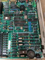
Usually documentation refers to graphics in this PC as Plantronics ColorPlus, but on the mainboard there's a PVC2 chip. System works in MDA, CGA and Plantronics modes. PVC2 also supports Hercules but as far as I remember it doesn't work.

What I'd like to know is whether PVC2 features can be turned on or off. I'd like to switch off CGA/Plantronics handling so I can try putting a VGA adapter in the machine's ISA slots.

Edit : Attached internet image of the relevant mainboard part
 

Attachments

  • s-l1600.jpg
    s-l1600.jpg
    443.7 KB · Views: 19
Hopefully, someone who is familiar with the Olivetti M19 will reply.

The only thing that I found is at [here], which suggests to me that having J1 and J2 open, might be the way to achieve what you desire.
 
Hey thanks for reply.

That same switch is also accessible at the back and is used when you plug in the color (CGA) screen. Because in "normal" case you use MDA monochrome screen but the card can still output color graphics to it.
Hercules support as far as I remember was never advertised for M19.

So if some Hercules clone cards use PVC2 chips how is CGA actually disabled in that case?
 
So if some Hercules clone cards use PVC2 chips how is CGA actually disabled in that case?
Chips like that can support a range of possible video outputs. Some examples at [here]. At power-on time, some software code somewhere has to configure the chip to output the desired video outputs.

For example, if I put a 'Hercules clone card containing a PVC2 chip' into my IBM PC, I am going to set the motherboard video switches to 'MDA'. Why? Because it is a Hercules card, not a CGA card. The actual electronics used on the card is irrelevant. When the computer starts, the POST in the motherboard BIOS will see that I set the motherboard video switches to MDA, and from that, know that it (the motherboard BIOS) needs to configure the video card to generate MDA outputs. (The CGA capability of the chip is simply not utilised.)
 
So if there are no mainboard switches, we come to baked in BIOS settings, which I was expecting.
Consider that I'm not interested in running two adapters and would be fine with BIOS not intializing the onboard circuitry at all.

Seems like patching the BIOS is the only option. I wonder how much of effort that is. There's a ROM dump available online.
 
So if there are no mainboard switches, we come to baked in BIOS settings, which I was expecting.
Jumpers or switches; it does not matter. A motherboard (or card) maker may choose to use switches, and some may instead choose to use jumpers. And for video functionality, the M19 has both. There are two jumpers (J1 and J2) and an 'external switch' ("EXTSW" printed on PCB). All are next to the motherboard's DE-9 connector.

What would make sense to me is something like:

- To use the DE-9 connector ("internal") for an MDA monitor, set the 'external switch' to off, and set J1 to closed, and set J2 to open. The POST will see that switch/jumper configuration and then configure the motherboard's PVC2 chip to output MDA signals to the motherboard's DE-9 connector. The motherboard BIOS outputs video to MDA.

- To use the DE-9 connector ("internal") for a CGA monitor, set the 'external switch' to off, and set J1 to open, and set J2 to closed. The POST will see that switch/jumper configuration and then configure the motherboard's PVC2 chip to output CGA signals to the motherboard's DE-9 connector. The motherboard BIOS outputs video to CGA.

- To use an EGA or VGA card (as the only video card), set the 'external switch' to on. The EGA or VGA card will configure itself (the card's BIOS ROM will do that). The motherboard BIOS outputs video to EGA/VGA.

Hopefully, someone who is familiar with the Olivetti M19 will reply.
Maybe there is someone out there who knows definitely what the story is regarding M19 video.
 
I'm pretty sure that's not what's happening here but I'll certainly be glad to be proven wrong. IMO ext switch jumper just allows you to control whether you can override whatever is set internally via an accessible switch. It does not mean "exernal graphics".

If you have both official screens Olivetti would not want someone to have to open up their case and tweak jumpers just to switch.

Edit : I'd also like more people with M19 experience to chime in, especially if someone own the sidecar expansion. The way I always understood, the sidecar has no active part in graphics, it's needed as power supply because CGA monitor has no built in PS for PC like mono one does. It actually only does this + full height ISA port. I remember seeing pictures off back of it, maybe because I had original manuals in the past, AFAIR there was only power connectors at the rear. So, for color you just plug in color monitor, and turn the external switch to color because in default configuration jumpers say "external switch on" which IMO means jumpers are not active, external switch is. If you flick that switch in runtime monitor just loses the signal, PC keeps running, flip it back, image comes up. Either that knob, or jumpers, in my view control only the CRT chip, not Paradise, which BIOS has no stake in. In "color" mode normal CGA signal is sent, while in "mono" mode signal is modified to allow CGA display on MDA screen. The switch does not control the BIOS mappings at all.
 
Last edited:
Info may be available in 86Box emulator which has M19 profile - or better said lack of info that onboard is designed to be disabled.


The machine is fixed to Plantronics module (which is in video/vga_colorplus.c).
I'll try modifying the profile and see how BIOS behaves if VGA is inserted.
 
Interesting that another graphics standard, e.g. "Olivetti Graphics Controller" is present throughout the code.
In 86Emu there seem to be two classes of ISA devices, with and without init. The without init seem to be fixed-logic components, init is with ROMs. The M19 video is implemented as non-init device. The code in that device maps 32kb from 0xb8000 to read/write callbacks and maps up I/O port 0x03d0 - 0x03e0 to in/out callbacks that change video modes.

If I replace that internal code for VGA device, the system boots up in VGA normally. I'll yet to test stuff. For now BIOS doesn't mind VGA.

I'm documenting a disassembly of the BIOS to see what exactly it does, if it does anything. I'll also do with the font ROM. It may contain configuration somewhere in there.
I'm also documenting the hardware as far as chips and connections are concerned.
 
Chip disposition is roughly complete. I have some unidentified.

Identified are : CPU, CPU controller, PIC, PIT, DMA controller, serial port and two video chips
Unidentified are Faraday 01-010053A and NEC D764AC-2. I have floppy, LPT and keyboard unaccounted for. They are probably for that.
With two ROMs, the rest is general purpose ICs.

I wonder about chips that have labels covering the model. Down south on the picture. Residing in the video RAM area. They have sockets.
Here http://www.vgamuseum.info/index.php/cpu/item/1034-paradise-systems-pvc2 we can see that smaller PVC2 indeed has one socketed chip right in the corner. The bigger Wang one does not.
What could be the purpose of inserting those chips in integration phase at OEM or wherever vs just soldiering them in production? I cannot find anything about the socketed Paradise chip.

Also M19 up right corner on picture, near the video port, has an empty socket. What could be the purpose of some IC there? The official brochure does mention composite video out and contemporary Olivetties did have one, could this be for that kind of an upgrade?

Note that apart from documenting the machine, switching off the video section and inserting VGA still remains a goal if it can be done in a non intrusive way.
 
Thanks I made a typo when noting down. D765AC-2, well documented FDD controller.
 
My m19 with monitor that I would sell for 200euro
 

Attachments

  • IMG_6864.jpeg
    IMG_6864.jpeg
    2.8 MB · Views: 7
  • IMG_6863.jpeg
    IMG_6863.jpeg
    1.9 MB · Views: 5
  • IMG_6862.jpeg
    IMG_6862.jpeg
    1.7 MB · Views: 4
  • IMG_6861.jpeg
    IMG_6861.jpeg
    1.7 MB · Views: 5
  • IMG_6860.jpeg
    IMG_6860.jpeg
    1.7 MB · Views: 9
  • IMG_6859.jpeg
    IMG_6859.jpeg
    2 MB · Views: 10
  • IMG_6858.jpeg
    IMG_6858.jpeg
    3 MB · Views: 9
Hello @fedefede .

There's a trade subforum too for this type of stuff.
I would be interested in getting it. The screen looks in far better condition than mine. Is floppy operational? You don't have original keyboard I suppose.

Are you in Europe?
 
Hello, I have also M19 but just standard version with two floppies and green monitor. For the 640x400 "Olivetti Graphics Controller" mode I can tell you that this is the same as on M24 PC. So you can run Windows 1.0/2.0 and GEM in this mode. Unfortunatelly I did not found any official technical documentation for M19 yet. Also for his "sister" the video typewriter system ETV 260 there is not much about the mainboard in it's service manual which I have. In any case what you need to know is that the M19 and so also the ETV 260 use a lower than CGA videi frequency, so you will not be able to use any other monitor on them as those Olivetti delivered with them. Even no NEC Multisync is that slow to display M19 / ETV 260 / ETV 500 (that is just a renamed 8 MHz cloked M19 which was connected to Olivetti ET series typewriters which acted as keayboard and printer) and ETV 3000 (that's a little bit changed 260) picture correctly. This explains the long lighning picture of the M19 monochrome monitor, this hides the low frequency.

ETV 260 ? I have two working ones of them, plus a sparepart machine and I have a working ETV 3000 as well. Look here, it is based on a slightly modified M19 mainboard. The main difference to M19 is that it runs at 8 MHz by factory.

Another difference of ETV 500, 260 and 3000 to M19 is that the BIOS does not support 5.25 inch 360 kB floppy but 720 kB 3.5 inch by default.

The jumper changes to switch M19 on 8 MHz are documented, see attached, but it is possible that some logic chips and the memory is too slow to switch every M19 board from 4.77 to 8 MHz.


Attachments

  • 33044.pdf
    212.6 KB · Views: 4
Last edited:
Hello and thank you very much for this information.

On the ETV, board is clean, there is no extra post-production wiring atop it. I wonder what's that difference all about.

For the CGA port, it will be worthwhile to check the colour signal with oscilloscope then.

In pursuit of hooking a colour monitor to my M19 I discarded using multisyncs anyway because they don't fit visually. I wanted to use a Olivetti 14" VGA screen of a bit later vintage but still visually fitting. GBS8220 upscaler is about to arrive and for CGA to work I need an addition anyway - https://github.com/jtsiomb/gbs-cgaega. Worth investigating if I can modify it to accept Olivetti frequencies.

Meanwhile I've poked around M19 reffering to PVC4 manual - http://ftpmirror.your.org/pub/misc/bitsavers/components/westernDigital/_dataSheets/PVC4.pdf. The registers are there, but most of them cannot be changed. Writes are done (with that read unlock procedure), but value is not changed. Depending on the whether machine booted in mono or in colour, and depending in what BIOS mode you are, you can write to appropriate register and it actually performs the change.

Been messing around with page switching in Plantronics mode. I think there's potential for some stuff to be explored since one mode is undefined by switches but page register works in it.

In any case this does seem like nothing in particular can be done. The graphics is pretty much baked in. Unless someone finds a PVC2 datasheet with pinouts, it's a dead end.
 
I wanted to use a Olivetti 14" VGA screen of a bit later vintage but still visually fitting
You won't get it to display anything readable, any monitor I tryed yet was out of sync. Even an original NEC Multisync 1 switched to TTL input. Modern TFT NEC Multisync which displays usually "anything" (NEC Multisync TFT 1970nxp) was out of range. Even a Philips CGA/NTSC/PAL (TTL+Analogoque RGB input, made for homecomputers like Amiga, ST and so) was not able to display that. No chance at all, the video line frequency is lower than 14 khz (standard CGA is 15.7 kHz), so no monitor except the original ones will sync them. And without the special afterglowing crt tube this would even flicker if it would sync.
 
Yeah I didn't suppose it can be directly connected even before your first post.
That's why I got a GBS8220. On the github link is TTL to to analog converter + sync combiner CGA/EGA input adapter, the input signal horizontal frequency I believe can be implemented in GBS8220 firmware (there is open source). EGA 21 kHz support must be added this way for example.

Interesting that there seems to be no ready, tested, documented option about connecting Olivetti M19 and alikes to generic screens.

Seems like the graphics on M19 are as about non-standard as a 'standard' CGA can be, very inflexible in terms of hardware replacement and repair ability. Doesn't have better graphics than Tandy but it's all dedicated hardware, something breaks, you don't have a spare, your computer is inoperable.

That kind of a situation is bad for IBM XT clone to be in 2023.
 
Hello, I have also M19 but just standard version with two floppies and green monitor...Unfortunatelly I did not found any official technical documentation for M19 yet. Also for his "sister" the video typewriter system ETV 260 there is not much about the mainboard in it's service manual which I have.

Is it possible for someone to reach to Olivrea or anyone else to ask for manuals and disks that they have on their site? I sent email to them once, didn't get a response.
There is no original user manual and floppies archived anywhere. I don't see why this should be the case. Can you share the ETV260 manual if it's not a problem?

Btw. my version is with 20MB HDD.
 
Back
Top