• Please review our updated Terms and Rules here

PDP11/83 in London storage

jonathanjo

Member
Joined
Feb 18, 2024
Messages
38
I have a few old PDP11s, none currently running.

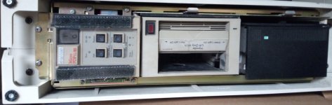
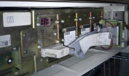
Finally I was able to get to my storage to take a few pictures of this PDP11/83 in vertical BA23. I bought it over ten years ago and have never even switched it on; it comes from Germany and has a Digital service log and so on.

The model plate says: Model 173QY B3 but there's also a label in German which says 183QE-DB.

I'm pretty good with equipment in general, but if there are any special precautions for this model I'm all ears.

Hoping I can get it soon to a convenient place to do at least preliminary power-on tests.

Kind regards,
Jonathan.
 

Attachments

  • front.jpg
    front.jpg
    170.3 KB · Views: 56
  • frontwithoutcover.jpg
    frontwithoutcover.jpg
    265.4 KB · Views: 56
  • rearbot.jpg
    rearbot.jpg
    530.9 KB · Views: 56
Last edited:
  • Like
Reactions: arf
other than the RIFAs in the power supply 11/83s are generally pretty easy to work with, there aren't many "gotchas" that i can think of right off the top of my head
 
Hi Jonathan
The PSU in the BA23 chassis has 4 Rifa caps that need replacing before you go near it with power and I suggest running it up slowly via a variac or 40/60/100W bulbs in turn for a few tens of minutes each to give the caps a chance to reform and not be too surprised by mains voltages...

But leave the PSU well alone unless you are comfortable with big dangerous switchers!

I'm in the UK, drop me a PM if you need help...

Robin
 
I took a look in my BA23 power supply a while back thinking I'd need to change out soon to fail RIFA caps, but found a different brand in there that used a different encapsulation material. Looked at my VAXstation 4000/60 and didn't find any RIFAs in there either.
 
I took a look in my BA23 power supply a while back thinking I'd need to change out soon to fail RIFA caps, but found a different brand in there that used a different encapsulation material. Looked at my VAXstation 4000/60 and didn't find any RIFAs in there either.
probably a different ECO, i know mine had them and they were pretty badly cracked
 
Thanks all, especially for comments about the possibly problematic capacitors.

Robin -- could you elaborate on this technique?
Radix said:
I suggest running it up slowly via a variac or 40/60/100W bulbs in turn for a few tens of minutes each

Obviously capacitors are used for lots of things: in these PSU's are they just suppressors, as suggested in this IT Garage article, and could be removed in the first instance?[/URL]

All in all, I think I'm not that comfortable with "big dangerous switchers"!
 
As a "cheat" alternative to full capacitor reforming, and to limit any pyrotechnics, you can use the "dull bulb" technique to limit both current and voltage to the unit - starting with a 40 or 60W real tungsten bulb (not halogens!) which will allow a limited amount of current and voltage instead of full mains.

To be clear, a tungsten light bulb is connected in series with the mains supply to the unit under test, add a lamp holder in the live supply and find some old bulbs. Do not use halogens, due to their very low cold resistance - or LED/CF bulbs.

The psu will not function properly, but the mains caps will get chance to reform by leaving it on like this for say an hour or more, before trying a 100W bulb, which on a lightly loaded PSU, will usually get the outputs pulsing or working at reduced voltage, with just one low power board installed to put some load on the +5V

A variac allows more precise control - but doesn't limit the current, if something goes "pop" - so a series bulb is still useful and shows if a fault or short has occurred by going out (open circuit) or full brightness (if there's a short) and generally, no big dramatic pops or blown fuses...

The voltages present in the PSU ARE STILL LETHAL and connected to the mains - so all the usual precautions are required.

I have done this on H786 and BA23 PSUs that nave not been used in decades and it works well.. Obviously look for signs of bulging caps and bad joints before doing this and sort those first.

Most supplies will work enough to see more or less correct voltages with a 100W series bulb and a low load on the output...

Some info here:

and more if you google "Dim bulb" or "Dull bulb"

and if you are not completely comfortable - get someone else to help! - I'm in the Midlands...

Robin
 
If you want to go the whole reforming rout its not that big a deal to pop out the two big electrolytic C1 and C2 and just use a bench supply to run them up gradually outside the power supply and then when satisfied with there state and after discharge reinstall them in the power supply. Be careful, they are big high voltage capacitors and pack a big wallop!

Capacitor reforming is like religion, ask two people about it and your likely to get at least three different theories about it. I do a lot of large systems and hardware that’s often been offline or stored for sometimes decades and find its always advisable to disassemble, clean and test everything before applying power but tend to think the idea of limiting in rush current or low voltage power up can sometimes cause damage to switching supplies, but that’s just me so your results may be different. But pulling the big filters out and checking and maybe reforming them outside the system is always a good thing.

Fortunately, C1 and C2 are easily removed.

The BA23 is a great frame to work on, easy to pop out the power supply and all that. Just remember that everything on the primary side of the power supply is at AC line potential and be careful because that that side of the power supply is HOT in respect to ground.

If you have a H7861 power supply you can pull C1 and C2, the 2000uf @200 volt capacitors and check them first. They are the primary filters for the high voltage for the switcher. C17, 11000uf @ 6.3 is the filter for the +5 bus but they tend to be trouble free like most of the capacitors on the secondary side of the power supply.

To check the high DC input to the switching supply read the voltage across the Test points on the Hot side of the power supply, That’s the + side of C1 and the – side of C2, that will be between two to three hundred volts DC, be careful! Don’t care how much you know or have done because that voltage can kill you.

Fun fact! The H7861 works on 120 or 230 volts AC, if you configure it for 230 volts mains its just a regular full wave bridge power supply but on 120 volts it’s a full wave doubler power supply.

Also check the condition of J2 and the Molex connector because I have seen a lot of heat damage around there on the output side of the power supply, at least on the 11/23 systems.

Beyond that the line input filter FL1 that the AC connector is attached to can be an issue but its sealed so when they get leaky they have to be replaced. The indication of a leaky FL1 is on a circuit with a GFI Interrupt the GFI will blow as soon as you plug in the power cable.

All my experience has been in the 11/23 H7861 systems but have done a couple, if its not a H7861 would think it may be similar but not certain, and working in the high voltage non isolated side of switching supplies is something that requires understanding of the risks and procedures for dealing with potentially lethal technology. Like working on old televisions or CRT Displays, without experience or training don't do it!
 
Thanks QBUS ... I take it you mean the marked caps on attached image, which is p38 of BA11-S Field Maintenance Print Set (MP-01233)

Also best photo I could get of exterior of PSU.

I clearly am going to need a bit of time to open it up and have a proper look; from what you're saying it's unwise to just try it.
 

Attachments

  • psu-layout-marked.png
    psu-layout-marked.png
    174.8 KB · Views: 11
  • psu.jpg
    psu.jpg
    303 KB · Views: 10
C1 and C2 are the two biggest capacitors on the power supply card. Also you can remove them just by unscrewing the two screws that attach them to the card. Disconnect everything from the back panel and from what i remember undo the two screws on the corners and the entire mess, power supply, card cage and everything pop out the front of the rack frame. you need to do that anyway to do all the cleaning, been a long time and don't remember if there was anything on the bottom but don't think so. The BA23 was designed for easy service, think DEC learned from the almost impossible to work on power supplies on the full size PDP-11
Do not know if the 11/83 or the Micro Vax used the same AC input box assembly as the 11/23 but DEC got a lot of use out of that case profile, card cage and power supply.
 
Am I getting confused and missing something - the H7861 is for the BA11 chassis - not a BA23 - that has an Aztec AA12131 (I forget the DEC p/n) - completely different and there are no diagrams for them... - Do you have both?
 
When I'm working on power supplies I typically use a fairly small isolation transformer (500VA). This provides the obvious earth current path via human protection but also significantly reduces the fault current if something goes short circuit. Depending on your electrical utilities source impedance, instantaneous fault currents can be quite high before a breaker will trip so having a spongy supply often turns a big bang into a small pop. Also great during testing since the initial inrush current is significantly reduced too so old components aren't subjected to as much stress.
 
Back
Top