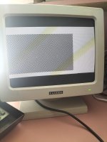
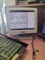
One thing about these 9" VDU's with that particular LOPT, the bias voltage for the brightness control was barely adequate and even when set at min brightness for the usual raster scan (which spreads the beam energy) it was pretty bright.(I modified mine to get the brightness lower). With V scan collapse the horizontal line you will see, even with that control set to min, will be harsh on the phosphor, if it takes too long to find the vertical scan fault.
I would recommend killing the CRT beam until you have fixed the vert scan fault.
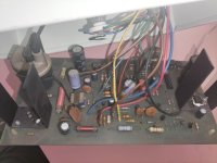
There are a few ways you can do this, disconnecting one of the CRT's heater connections will work as that kills the electron emission. But probably the easiest way is to disconnect the H drive pulse, this will simultaneously kill the high voltage supply, kill the EHT and the H scan too. Simply lift one leg of the H drive input coupling capacitor C16 from the pcb. And connect up last thing after the V scan fault is fixed or at least you have some vertical scan. So there will then be no -30V, no +85v and no 10kV EHT and the horizontal driver transistor Q13 and H output transistor Q14 will both be in a non conducting condition. The CRT heater will still be glowing with no other voltages on its other electrodes, this does not harm it. But, the V scan stages do not depend on any of these voltages, only the +12V. This will also make it safer for you to work on too.
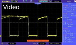
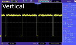
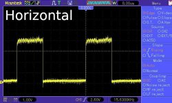
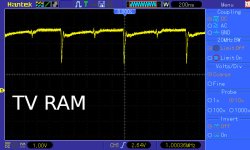
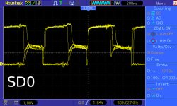
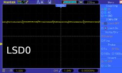
Then you can, using the scope, trace the vertical drive signal through the vertical amplifier and output stage, to find out what has gone wrong there. If you posted scope images of those, we could collectively work out what has gone wrong.
Generally, for this is, an open circuit wiper connection on the height control preset does not result in full scan collapse because they have connected the wiper to one side of the preset, but it is worth checking.
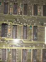
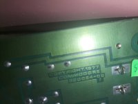
(you have probably also noticed by now that the copper trackwork overlay diagram with the component locations, has been left-right reversed or flipped. This copy on Zimmers is the only one I could find, I wonder if that mistake was in the original service manual, I think it must have been and wasn't noticed. There is no easy way to fix that diagram, without a lot of work in photoshop. Also if you want to fix the brightness control range later, to get a lower brightness, there is a simple mod adding a few extra turns around the LOPT core to get the -30v rail up to around -45v which is required to cut-off the beam in the green Amperex GH suffix CRT, but not sure about the white 9VALP4 CRT as I don't have one. Later it is also worth increasing the filter electrolyic cap value on that supply rail to prevent the notorious late turn off spot)
")