• Please review our updated Terms and Rules here

Pet 4032 repair time

arnuphis

Experienced Member
Joined
Sep 1, 2020
Messages
55
Hello everyone! I have a 'fat 40' 4032 which I am bringing back to life.
I decided to use a MiniPET board for now and look at the mainboard later.
So the miniPET chirps happily when powered from the PET PSU. I checked all the settings to be a NTSC 12" Pet.
The CRT tube lights up but there is nothing on screen.

What's a good first step to test? Before I start messing with the video board itself I assume we need to look at voltages to it?
Once I get the CRT working with the MiniPET I can then look at the original board.

Thanks in advance.
 
The first thing is to check the H, V , and video drive signals are present and being fed to the VDU. As I recall some of the VDU's are notorious for fusible resistors going open circuit with age.
If you could find the schematic for your VDU and post it, that helps with the fault finding.
 
So, I am a bit confused...

The miniPET can drive a 'real' PET monitor and has a standard composite video output.

What output are you using with which monitor?

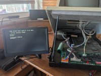
Perhaps a photograph of your setup and how it is cabled?

That Hitachi monitor you quote has a composite input (if I remember correctly).

Dave
 
Yes. The MiniPET does drive a real PET Monitor. That is how I had it running in my 2001-8. Hooked up to existing keyboard/video cables and power and it worked great. On the 4032 I have it hooked up the same way but nothing is showing on screen. CRT heater lights up but that is it. So that is why I am looking at the video board. I can send a photo later of everything if that helps.
 
I can't see how post #3 fits then?

There is a possibility (since you mention that it worked on a 2001-8).

Commodore PET computers sometime change the polarity of the HDRIVE, VDRIVE and VIDEO signal depending upon which monitor is fitted.

Are there any options in the miniPET to change the polarity of the signals it produces?

Worth a test? But note down how it is configured now...

Dave
 
CRT heater lights up but that is it.

That is slightly different to what you originally said, as you seemed to be suggesting that there was a raster on the screen... 'CRT lights up'.

If this is the 12" monitor, then as has already been mentioned there is a very common problem with open-circuit failure of two 56R resistors on the monitor PCB - part numbers R752 and R753 spring to mind. If you find them open-circuit, buy not just two but a few more. Sometimes replacement of the resistors is all that is needed but sometimes one of the associated electrolytics C752 / C753 fails leaky and if so the resistors will burn out again - hence the advice to have a few spare resistors handy.
Thanks. I will look into this. Do you have the part numbers for the resistors/capacitors? I don't have a schematic to work from.
 
You need to tell US what you HAVE.

We are not mind readers - although this would be a useful skill to have :)...

Can you take a photograph of the monitor PCB and identify any numbers/text on it please?

Once we identify the monitor PCB you have, we can point you to the correct schematic...

You will find most of the schematics over on this very useful website (if you have not found it already): https://www.zimmers.net/anonftp/pub/cbm/schematics/computers/pet/index.html.

Also, what is the assembly number on the logic board that you removed from the PET.

I am assuming your monitor is a 12" diagonal. Is this correct?

Dave
 
Last edited:
You need to tell US what you HAVE.

We are not mind readers - although this would be a useful skill to have :)...

Can you take a photograph of the monitor PCB and identify any numbers/text on it please?

Once we identify the monitor PCB you have, we can point you to the correct schematic...

You will find most of the schematics over on this very useful website (if you have not found it already): https://www.zimmers.net/anonftp/pub/cbm/schematics/computers/pet/index.html.

Also, what is the assembly number on the logic board that you removed from the PET.

I am assuming your monitor is a 12" diagonal. Is this correct?

Dave
I already provided the info for the Video board in post # 3. It's a Hitachi SP MCL-437F. I will get the system board info later and photos.

Thank you for the link btw.
 
That is why I am querying the monitor...

To me, the Hitachi SP MCL-437F has a composite video input - not the standard Commodore HDRIVE, VDRIVE and VIDEO inputs. It looks way too complicated (or at least the photograph that I have seen of the monitor electronics) to work with a 'standard' PET. I may be wrong.

Is it possible that your original PET board had a PET to Composite video unit fitted and the monitor CRT and electronics changed for the Hitachi unit?

I am just trying to understand your particular setup, and something is not sounding correct to me...

Dave
 
Last edited:
If it is a Hitachi branded monitor then it is unlikely to be the standard 12" Commodore one to which my comments in #8 about the resistors apply, sorry.
 
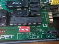
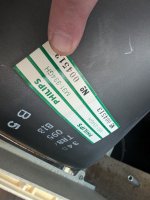
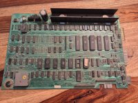
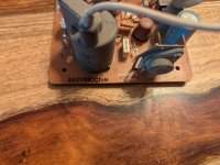
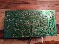
Sorry to be so obtuse. It's not on purpose! Anyway I hope these photos help. And yes 12" screen.
 

Attachments

  • PXL_20240628_003939627.jpg
    PXL_20240628_003939627.jpg
    2.3 MB · Views: 12
  • PXL_20240628_003951935.jpg
    PXL_20240628_003951935.jpg
    1.9 MB · Views: 11
  • PXL_20240628_191034033.jpg
    PXL_20240628_191034033.jpg
    2.3 MB · Views: 11
  • PXL_20240628_191114220.jpg
    PXL_20240628_191114220.jpg
    4.6 MB · Views: 13
  • PXL_20240628_191125592.jpg
    PXL_20240628_191125592.jpg
    3.2 MB · Views: 13
  • PXL_20240628_191132057.jpg
    PXL_20240628_191132057.jpg
    2.9 MB · Views: 11
  • PXL_20240628_191144212.jpg
    PXL_20240628_191144212.jpg
    3.3 MB · Views: 10
  • PXL_20240628_191147931.jpg
    PXL_20240628_191147931.jpg
    2.5 MB · Views: 12
So your logic board is a Universal 2 found in the 'univ2' directory.

The brown monitor PCB is the display_321448.pdf schematic and parts layout (found in the 'univ' directory).

Not sure about the green PCB, but it is for a Commodore. Can you photograph the component side of the green PCB so I can perform a 'pattern match' on the PCB layouts we have?

Dave
 
By the green PCV I assume you mean the monitor PCB? It's brown on the topside and that is photo 5 and 6. I will take a look at the diagrams over the weekend. Thanks again for all the help so far. Owe you a virtual pint already.
 
That's very weird having a brown top and a green solder mask on the bottom!

Excellent, so we know what it is now...

It's bedtime in the UK now, so I will pick this up tomorrow.

Dave
 
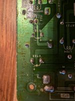
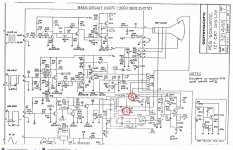
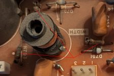
I put some rings around two of the fusible resistors that often go O/C in these VDU's. If you cannot get the correct part simply replace them with small 56 Ohm 1/8W rated parts, these make good little fuses when overloaded but mount then about 1/4 inch off the board surface.

The schematic is a little patchy for the component ID numbers. Check initially the three resistors on the pcb (photo)

You CRT has the European designation for the phosphor, suffix GH, which is the equivalent of the American P31 green, or P1 green. But actually I have found the mix is not exactly identical and the GH tubes do produce a very pretty shade of green. Also, the design of the VDU is good in that it has Dynamic focus, to improve the focus across the whole screen, and it has a magnetic linearity coil ( some early 9" PET VDUs did not have these refinements)
 

Attachments

  • FR.jpg
    FR.jpg
    353.6 KB · Views: 8
  • FR2.jpg
    FR2.jpg
    222.8 KB · Views: 11
Last edited:
I have the usual suspects for testing. Multimeter and an oscilloscope which I am still getting the hang of. I was planning to look at a logic probe once I turned my attention to the Pet board itself.

I have company here for the US holiday week so time is limited but I will check in on those resistors once I get a chance and order in some replacements just in case. Will report back once I have spent some more time on the project.

Thanks again for the help so far. You are very appreciated!
 
Back
Top