• Please review our updated Terms and Rules here

Pet 4032 repair time

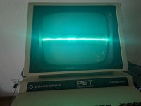
Update. We are making progress! Good call on the resistors as two of the three were bad. Replaced all three and below is the display after power on. Turned it off quickly as it got very bright. Quite a nice collapse there don't you think?
 

Attachments

  • PXL_20240712_163449736.jpg
    PXL_20240712_163449736.jpg
    2.1 MB · Views: 3
So, you now have HDRIVE... Well done.

Now what about VDRIVE?

Use your oscilloscope and check the VDRIVE signal to make sure that it is present on the monitor PCB.

We decided this was the schematic: https://www.zimmers.net/anonftp/pub/cbm/schematics/computers/pet/univ/display_321448.pdf.

If you look at the schematic from where VDRIVE enters, you should observe the following numbers in circles: 3, 6, 4, 5, 7, 8, 9, 10 and 11.

These refer to oscilloscope traces as described here: https://www.zimmers.net/anonftp/pub/cbm/schematics/computers/pet/univ/display_waveforms_321450.pdf.

Not sure what happened to numbers 5 and 6 - they seem to be missing...

Dave
 
Last edited:
Back
Top