• Please review our updated Terms and Rules here

PET 8296D chirp sound ok at boot but only raster on screen

demonlg

Veteran Member
Joined
May 22, 2016
Messages
521
Location
Italy
Hello all, another 8296 but in this case model D (inside disk drives)

I have recapped powersupply and i have all good line rail 5v and 12v and power for monitor board. But, the system boot with complete chirp chirp, it's reset if i press reset button and then it chirp again, monitor starts with raster and retrace lines only when i move luminance trimmer, but don't show any text.

Now, all socketed chip tested on other 8296 and all are good, CPU(tested with three different), PLA's (used in other 8296 and tested), 6545 CRTC (thested with three different).
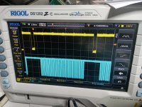
I have checked signals on video connector and all are present. If need i post photo of the three signals VIDEO, VSYNC and HSYNC.

I check also video signals on the CRT BOARD, and all component in VIDEO area and to CRT tube are good.

Any help is appreciated.

Emanuel
 
Adding, i have inserted the PETTESTER ROM and have same results (without chirp boot sound)
 
If the HDRIVE, VDRIVE and VIDEO signals are present, there should be a picture on the display then. Yes?

What results do you see with my PETTESTER installed?

Dave
 
Only raster and retrace line if i put high luminance, same with original edit rom installed, but i don't khow if the signals are ok, i have confronted signals of other 8296 but I think there are some differences, I'll see if I can post the photos.
 
Post the photographs and the oscilloscope traces please.

Let's get some data points to start with...

Dave
 
Ok, i have to reinstall CRT board on the CRT and i send you image of screen, now i have only possiblity to send scope trace.
 
Little video clip

161049 is VIDEO signal
161127 is VERTICAL DRIVE
161205 is HORIZONTAL DRIVE

This is with original EDIT rom installed. (NOT PETTESTER!)
 

Attachments

  • VID_20240415_161049.mp4
    4.2 MB
  • VID_20240415_161127.mp4
    4.6 MB
  • VID_20240415_161205.mp4
    5 MB
HDRIVE and VDRIVE look to be fine.

There also appears to be some black and white video on the VIDEO signal.

Dave
 
The video signal is transitioning from the black level to the white level.

The black level could be either where the video signal should be blanked (i.e. when HDRIVE or VDRIVE is 'flying back' the electron beam) or black pixels on the screen. The white level is an illuminated pixels on the screen.

What I am saying is that the VIDEO signal is not 'stuck' permanently HIGH or LOW.

Dave
 
Ok, i have to chop the video signal with H and V drive? This night i reassemble the monitor board and send you photo of screen.
 
This is the yellow video signal and cyan vertical drive in video 194153 and with horizontal drive in video 194550.
 

Attachments

  • VID_20240415_194153.mp4
    3 MB
  • VID_20240415_194550.mp4
    3.9 MB
I am not sure what you are doing...

I would use the VDRIVE signal as the trigger point for the oscilloscope (say channel 1 configured to trigger from LOW to HIGH) - then adjust the oscilloscope timebase to get a few pulses of the HDRIVE signal (say 10 pulses) displayed on channel 2.

Select CHOP mode so that we get the two (2) oscilloscope channels aligned in time.

Then move channel 2 from the HDRIVE signal over to the VIDEO signal.

This should display 10 lines of the video signal from the top of the monitor (approximately the first line of text.

Dave
 
I don' know if i understand but now i have restarted test with your pettester rom inserted, i have connected on ch1 yellow the vdrive signal with two negative pulse by move time base to 2ms, then i have connected ch2 cyan on video signal, and i have this.

In the video you see the pulse on ch1? I think so it is a pulse generated by your countdown in pettester rom.
 

Attachments

  • IMG_20240415_235520.jpg
    IMG_20240415_235520.jpg
    2.8 MB · Views: 2
  • VID_20240415_235531.mp4
    3.9 MB
It's normal video signal is 60hz and in other post of 8296 repaired i have 50hz? Different rom?
 
I am in the UK, so the default programming for the CRTC is 50 Hz...

You haven't quite configured your oscilloscope according to my specification.

Move the cyan probe from the VIDEO signal to HDRIVE.

Make sure the YELLOW VDRIVE signal triggers on the LOW to HIGH part of VDRIVE.

Adjust the oscilloscope timebase to get 10 HDRIVE pulses on the cyan trace.

Then move the cyan probe from HDRIVE to VIDEO.

Dave
 
Sorry for my mistake but I thought I did it right in the last image, I'll try again later
 
Sorry Dave but is correct this?

Make sure the YELLOW VDRIVE signal triggers on the LOW to HIGH part of VDRIVE.

or

Make sure the YELLOW VDRIVE signal triggers on the LOW to HIGH part of HDRIVE.

I don't know why i don't understand ! :D
 
Back
Top