daver2
10k Member
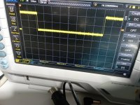
A signal that starts at +5V, then goes to 0V for a short while, then goes to +5V again has two 'edges'.
One goes from HIGH to LOW and the other one goes from LOW to HIGH.
The edge that goes from HIGH to LOW signifies the START of the vertical flyback period. The edge that goes from LOW to HIGH signifies the end of the vertical flyback period and the start of the first horizontal line of pixels on the screen.
We are not interested in the vertical flyback period, but in the line of pixels on the screen.
We therefore need to tell the oscilloscope trigger to look for the LOW to HIGH transition of the VDRIVE signal to trigger on.
We are going to run the oscilloscope timebase quite fast to see a few lines of pixels on the oscilloscope screen. However, if we trigger on the wrong part of the VDRIVE signal we will get a load of irrelevant time of nothing on the oscilloscope screen.
We avoid that by telling the oscilloscope to trigger at the point in time where the 'interesting' stuff is!
Dave


