• Please review our updated Terms and Rules here

PET 8296D chirp sound ok at boot but only raster on screen

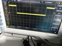
A signal that starts at +5V, then goes to 0V for a short while, then goes to +5V again has two 'edges'.

One goes from HIGH to LOW and the other one goes from LOW to HIGH.

The edge that goes from HIGH to LOW signifies the START of the vertical flyback period. The edge that goes from LOW to HIGH signifies the end of the vertical flyback period and the start of the first horizontal line of pixels on the screen.

We are not interested in the vertical flyback period, but in the line of pixels on the screen.

We therefore need to tell the oscilloscope trigger to look for the LOW to HIGH transition of the VDRIVE signal to trigger on.

We are going to run the oscilloscope timebase quite fast to see a few lines of pixels on the oscilloscope screen. However, if we trigger on the wrong part of the VDRIVE signal we will get a load of irrelevant time of nothing on the oscilloscope screen.

We avoid that by telling the oscilloscope to trigger at the point in time where the 'interesting' stuff is!

Dave
 
So, let's go step by step, let's take the first step first, this is vdrive, is what I'm viewing in this photo what you're asking me about vdrive?
 

Attachments

  • IMG_20240416_220059.jpg
    IMG_20240416_220059.jpg
    3.2 MB · Views: 3
Hi Dave, I can't possibly set my scope as you asked, I really don't know how to do it, the only thing I can see is what I attached in post 15, I just can't.
Tomorrow I will probably be able to reassemble the screen, I had to replace a diode which was completely detached due to oxide on the leads, but I don't know how to see if the signals going to the screen are ok.
I know I ask too many questions but in context I'm also trying to learn, I'm not expert with the oscilloscope, so I don't know if I'm doing everything correctly or not.
I don't understand if I have to do the measurements with the PETTESTER rom installed or if I have to do them with the original edit rom, but from what I can see on the scope it seems the same to me.

My scope has several triggering functions, but it's not clear to me how to use them for the purpose you asked for.

I would like to fix this computer, I don't have to sell it, it's mine, and I would like to get it back into operation, what I can't understand is whether the problem is with the computer or with the monitor.

Can we do it more simply for me?
 
I am still away on my business trip. On my way back home shortly, so we can reconvene tomorrow.

Your oscilloscope can be set-up correctly, but we can go slower.

There is another recent PET thread where we have taken exactly the same measurements.

Dave
 
Yes, I remember that we also took them for the other 8296, in fact I tried to do the same measurements as in post 15 of the other discussion, but what I get is what I posted, and it's the same thing with both PETTESTER than with the original EDIT.
 
Hi Dave, i have repaired the video board and now i have a video image in photo, probably any issue in char rom section or ram. The char rom is good.

Any idea?
 

Attachments

  • IMG_20240420_085456_957.jpg
    IMG_20240420_085456_957.jpg
    806.9 KB · Views: 1
  • IMG_20240420_085556.jpg
    IMG_20240420_085556.jpg
    2.2 MB · Views: 1
With PETTESTER it's pass first 2 test and going to countdown and then ram test.
 

Attachments

  • IMG_20240420_091430.jpg
    IMG_20240420_091430.jpg
    3 MB · Views: 2
  • IMG_20240420_091627.jpg
    IMG_20240420_091627.jpg
    2.6 MB · Views: 2
So the problem is in the video section.

Not the interface between the 6502 CPU and the video RAM though.

The signal path from the video RAM output to the character generator most likely.

I will have a look at the schematic after lunch and ask you to take some measurements.

Dave
 
It looks like you have a data bit 7 stuck HIGH on the EVEN VIDEO RAM (permanent inverse video) and an address bit 0 problem as well (duplicate characters between the ODD and EVEN RAM).

Dave
 
This is an 8296 of course, so the video RAM is the main RAM.

I would look at UC6 and UC7 (74LS374). These devices latch the ODD and EVEN data for successive characters.

I would specifically check the signal identified as RVS and what is happening on UD7 (74LS14) pins (1 and 2) and (3 and 4). Both of these gates are inverters.

Dave
 
Yes, found a defective UC6 74ls374 dave! Now is ok. Wow

It's time to revive drives unit now.....
 
Back
Top