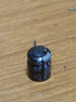
• Please review our updated Terms and Rules here

Pet 8296D no signs of life

I found a small 33uF capacitor which is a bit swollen .. I try to replace ..
 
I would also be interested in a similar photograph of the other side of the PCB. I will see if I can follow the enamelled copper wires for the stator coils to see if I can work out where they go. We can measure the resistance of the coils then to see if one is open circuit (or intermittent). I will hopefully then be able to find the driver IC for the stator coils.

Dave
 
Excellent.

Is that a short circuit solder joint I see on the right-hand side?

1668799032874.png

The very nice circular pattern is the speed sensor coil I suspect.

Dave
 
Is that a short circuit solder joint I see on the right-hand side?
No it isn't! It's only bit of capacitor leg ... but it doesn't touch the other circuit ... I also changed the 33 uF capacitor which was swollen ...
 
This is 33uF capacitor that i replaced:
 

Attachments

  • 1668799874350..jpg
    1668799874350..jpg
    685 KB · Views: 4
Right. I have identified most of the components within the motor drive circuit.

The main IC is the TA7245BP with the two metal tabs (heatsink). The data sheet is here: https://datasheetspdf.com/pdf-file/499880/Toshiba/TA7245/1.

Check capacitors C13, C14 and C15 for signs of short circuits or low resistance (using your multimeter with the power OFF).

Pins 6, 7 and 8 of the IC drive the sets of coils (three in total wired as three sets of two individual coils in series).

Pin 12 is the motor ON/OFF control signal.

There are three (3) sensors (marked as HV, HU and HW) on the board. Can you see any part numbering on these components? I am just wondering whether they are hall effect devices (magnetic) or opto sensors?

These are wired back to the TA7245BP and are used for speed control (not the zig-zag PCB track that I saw on the solder side of the PCB).

Dave
 
Check capacitors C13, C14 and C15 for signs of short circuits or low resistance (using your multimeter with the power OFF).
Capacitors are ok!
There are three (3) sensors (marked as HV, HU and HW) on the board. Can you see any part numbering on these components? I am just wondering whether they are hall effect devices (magnetic) or opto sensors?
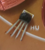
Unfortunately there is nothing written above these components :(
 
These is a sensor:
 

Attachments

  • Screenshot 2022-11-18 alle 21.03.39.png
    Screenshot 2022-11-18 alle 21.03.39.png
    337.4 KB · Views: 1
Maybe after 33uF cap replacement, can i try to remount the drive and test?
 
Can I suggest before you do that to note down the orientation of the IC with the two metal tabs on it so you know where pin 1 is when you have remounted the PCB and you are looking at the pins from the bottom.

We can then do some tests if (when) the drive doesn't work.

Dave
 
Success! After 33 uF capacitor replacement, drive 1 is now working! thanks so much!!
 

Attachments

  • 1668855701745..jpg
    1668855701745..jpg
    1.2 MB · Views: 5
I am surprised, but if it works for you!

See, no need to get desperate again!

Well done. So, what have you learnt from this repair?

Can you post a picture showing which capacitor you replaced? Use one of the photographs you have taken previously and just identify the capacitor in some way. I will then try and work out what the capacitor does. This will confirm that the 'repair' accounts for the observed fault, or whether this was just random luck and the fault may still be lurking.

I am guessing it was capacitor C12?

Dave
 
Last edited:
Well done. So, what have you learnt from this repair?
Hi Dave, I learned that the first thing to do (without despair) is to take a good look at the board and look for any damage :)

Yes is C12 capacitor!
 

Attachments

  • IMG_20221118_184503.jpg
    1.5 MB · Views: 5
Back
Top