Desperado
Veteran Member
- Joined
- Nov 25, 2017
- Messages
- 6,827
Hi Dave, please how can i test this controller??The motor should be wired to a speed controller circuit (as the last one we repaired was).
Dave
Hi Dave, please how can i test this controller??The motor should be wired to a speed controller circuit (as the last one we repaired was).
Dave
That is an unnecessary question. With all that you have been taught, you should review the last drive troubleshooting with the speed controller, and try to repeat the steps using the proper schematic. If you hit a dead end, then it is fair to ask a question based on the new troubleshooting.Hi Dave, please how can i test this controller??

Hi Dave, this is different respect the other driveThat is an unnecessary question. With all that you have been taught, you should review the last drive troubleshooting with the speed controller, and try to repeat the steps using the proper schematic. If you hit a dead end, then it is fair to ask a question based on the new troubleshooting.
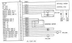
PIN 1: 5VPin 4 (BLACK wire) to your multimeter BLACK lead.
Measure pin 1 (RED wire) - It should be approximately +5V.
Measure pin 3 (ORANGE wire) - It should be approximately +12V.
Measure pin 5 (WHITE wire). This should be HIGH (when the motor is not running) and should go LOW when the motor should be turned on.
Desperado,I am desperate!!! Where i can found a replacement drive for my 8296D ???
No Dave i have 5V on pin5 in normal mode..Desperado,
Are you saying that when you tried a Directory command to that drive, Pin 5 stayed High?
But if i must measure pin 5, i need to remove drive s' connectorThen so far so good. Monitor pin 5 with the scope, while you attempt a Directory command to that drive with a good disk inserted. Do you see a negative pulse on pin 5 (/Motor on)?
but it certainly looks like it.Rome wasn't built in a day...
Dave
But Cbm Pet 8296 yes!! ehehRome wasn't built in a day...
Dave
