• Please review our updated Terms and Rules here

PET 9" Monitor, losing vertical deflection randomly

Hutch

Experienced Member
Joined
Jul 1, 2018
Messages
311
Location
California
Seems to be losing vertical deflection. Been getting steadily worse over time and seems better when it's cold vs when it's warmed up.
Was thinking about re-capping but I know there are some caps that require very low ESR and may be hard to find.
Not sure what I should be looking for at Mouser or DigiKey to be sure I get the right specs.

Do you see anything in the video that points to a particular component or area?
Thanks.

Video Link: https://youtu.be/gECCG7t_qdU
 
Yes I have had something similar. It turned out to be a combination of IC’s in my case not capacitors.
I replaced D8 (vertical drive) and that temporarily fixed it but then I think E5 failed (screen collapsed to half the size) after that..... from what I recall.

Andy
 
I'll break out the scope and see what's happening with H & V sync when the picture jumps.
I didn't consider a problem with the digital side since I'd expect it to work or just not work at all.
 
Are you losing the vertical drive signal (60 Hz) from the mainboard? If so, it is generated by some complicated sequencer logic (see middle of sheet 3) composed of flip flops and counter chips and a failure of any of those chips can cause those symptoms. If the vertical drive is steady then the problem will be in the video board. The horizontal signal circuit is much simpler and is usually OK in the main board.
 
In a similar case I had, it was a marginal CR8 on the monitor's PCB. It might also be some intermittent solder joint on either (or both) the main PET board or the monitor board.
In any case, it can't be easily solved without checking where the fault lies. A logic probe could help understanding if the fault is caused by loss of the vertical drive from the mainboard. An oscilloscope would help finding the fault wherever it lies.

Frank

PS: I think also a cracked R20 did a similar effect on another of those monitors.
 
Last edited:
I hooked the scope up to the vertical sync pin on the logic board.
Normally the vertical pin is 5v with negative pulses to ground at 60Hz.
I watched it until it warmed up enough to start doing it and when the picture collapses vertically, the pulses stop and it's a steady 5v
but sometimes it drops to a steady ground level and when that happens there's no picture at all.
So I guess the problem is on the logic board in the area around D8 or B6.

I assumed it was something in the CRT so I was looking there.
Thanks for the re-direction.

p.s. it does it even with the monitor unplugged, so it's not being dragged down by something in the CRT.

I guess I'll start tracing signals back from v-sync.
 
So I guess the problem is on the logic board in the area around D8 or B6.

Exactly right. Unfortunately when a state sequencer stops, it is hard to tell cause from effect.

You will have to go down the counter outputs from chips D5, D6 and D7 looking for a struck output. Try to ignore chip E6 (74100) for the moment. It holds the starting address of character rows (i.e, decimal 40, 80 120) so they can be repeated for eight scan lines to form a character row. Lets hope right now that the 74100 is not the problem as it is confusing. It is probably a bad counter or logic gate that is causing the problem. The 74177 counters are high failure items.
 
Strangeness. My scope kinds sucks. It's a very old 20MHz analog scope so it may not be fast enough for me to see what's happening but ....

I can't see anything on the Q output (pin3) of C7. Nada. But I do see toggling on Q-not. That output drives the flip-flops at B6 so I know there has to be a signal there.
It's tricky waiting for something to happen.
I was looking at the Q output (pin3) of the flip-flop at B6 and I was seeing the normal 60(ish) Hz pattern there while the picture was stable and when it finally collapsed, I was getting something MUCH faster. Like 250KHz.
I don't know what frequency would normally be clocking that flip-flop but could it fail in a way that passes it's clock through or is something else down the line running faster?
I can't figure out why I can't see any signal on pin 3 of C7 or pin 12 of B6. I probably just need a new scope.

Also note: When the picture collapses, I don't lose H-Sync or video.

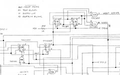
schematic.JPG
 
The C7 pin 3 flip flop output is a key signal to clock the two B6 state sequencer flip flops. When it stops, it usually means the sequencer is struck due to a problem somewhere in conditions leading to the next step. However if the Q/ is toggling and the Q is not, let's hope that you found the problem and the C7 is bad. Change it!
 
The four states of the B6 flip flops are listed on the top of the page next to B6. When things are working it takes 16.66 mS to go through the four states which gives the Vertical Drive 60 Hz signal. The counters I mentioned previously are used to determine the timing of the states and also are used as addresses for the video memory refresh circuitry.
 
The confusing thing is that if there are no state changes on C7 pin 3 - then the whole of B6 should be static. You shouldn't see any of these gates changing state and you should not have any vertical drive.

I can see this failing during a fault - but (under normal image conditions on the monitor) you should see a regular clock on C7/3.

Dave

Hi Daver,
I think he is saying he sees no clock when the 'screen collapses'. When the sequencer is working, the C7 pin 3 output will generate a clock pulse for each state. The states are named Vertical Drive/, Top Blank, Video On, and Bottom Blank. This repeats every 60 Hz.
 
I have witnessed PET owners work for a month to fix a problem with this sequencer because when it is stuck, it is difficult to see what is wrong as everything looks bad. Our guy may be lucky he spotted an obvious bad looking flip-flop (Q and Q/ not compliments). Let's hope.
 
To clarify, ... Even when it's working properly and the picture is stable on screen, my scope can't see anything on pin 3 of C7.
Which makes it difficult to troubleshoot since I can't see a difference between when it's working and when it's not.

Clearly if there was no signal on pin 3 of C7, there couldn't be a V-Sync signal, but there is, so I have to assume the problem is with my scope.
However I can see a signal on pin 2 so I don't know what to think. All the while the picture is stable.

What frequency would you expect to see at that point? (C7, pin 3)

Any idea why, when the v-sync does drop, I'm seeing ~250KHz on the output of B6?
 
Hutch,
But then you said you COULD see the compliment signal out of C7- pin 2?? That should just look like a negative glitch compared to the positive glitch from C7= pin 3. Maybe you are just not syncing correctly? Fiddle with the trigger adjustment.
 
Any idea why, when the v-sync does drop, I'm seeing ~250KHz on the output of B6?

If the B6 outputs were going at that rate, you would see a vertical sync pulse every 16 uS instead of about 16 mS. The screen would definitely have problems/collapse!

EDIT: If so that would lead me to suspect that something is forcing the D8-pin 6 NAND gate output to be stuck high. This is a key gate that tells the sequencer it is time to go to the next state. If struck high, the sequence would run way to fast. The gate is at the bottom of the schematic page. I thought this fix was looking too easy :) . Hang in there, we'll get this bug!
 
Last edited:
Confusing. C2 and D8 are marked as 74LS00 but in some places they are drawn as NOR gates and others as NAND gates.
I guess it works out to be the same thing?
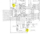
schemat.JPG
 
A little confusing, but not a problem. It is shown as a 'demorgan' of a NAND gate and is equal. Actually shown for clarity as this gate is used in this circuit as an 'OR' function with negative active inputs. When any input goes LOW, the output goes HIGH.

With the D8 gate, it is saying when either input pulses low, a positive pulse will be generated to clock the sequencer to the next state. Then C6 is saying OK, but only at the end of the next horizontal scan, and C7 then says OK but wait for next synchronizing 4 Mhz clock.
 
Last edited:
I don't have the replacement parts yet, but my working theory seems to be gaining ground.
It occurred to me that a possible reason I wasn't seeing anything on the Q output on pin 3 of C7, might be if B6 was overloading the signal and dragging the voltage down.
The scope can't see current and it still could be driving B6 with current even if the voltage was low.
Is that even a possibility?

In any case, after removing the 107 from B6, I CAN now see the output from C7, so ....
New LS107, LS00 and LS08 chips arrive on Wednesday.
 
Back
Top