• Please review our updated Terms and Rules here

PET EDIT ROM test firmware.

daver2

10k Member
Joined
Jun 19, 2012
Messages
16,408
Location
UK - Worcester
I have finally got around to finishing the documentation for my PET EDIT ROM test firmware.

The 'official' Version is V04 and the source, binary, HEX and documentation can be found on my google drive at https://drive.google.com/drive/folders/1fyLbr1kcG98a2FDOMo1H5pj9lIdJpHcx?usp=sharing.

I hope this is of some use to the Commodore PET community in diagnosing and fixing faults so that we can keep these treasured machines in a state of repair for the future.

Bo, any chance of you copying these files to your website?

Enjoy :)!

Dave

Thank you Dave!
 
>>> Thanks for this. I hope I never have to use it.

But I know a lot of people who have...

>>> Thank you Dave!

No problem.

I am going to have a rest (and fix my 8032) before I have a go at V05...

Dave
 
BTW Dave, I've noticed the first two or three screens are quite fast, about 1 second everyone; almost impossible even to take a picture...

Is there any way to slow down this part?
 
>>> Is there any way to slow down this part?

There is, but then I would get complaints about holding the test up when there is nothing wrong! You can never please all of the people all of the time I think the saying goes...

The idea was a fairly brief delay - as the PET hasn't detected anything wrong at this point (i.e. the screens will indicate everything is all good, so there should be nothing for the tester to really see - apart from a load of 'G' or 'g' characters on the screen for the memory tests).

The exception to this rule could be where the CPU can correctly write to (and read from) the screen memory - but what is displayed is in error. This case should be revealed by the ROM checksum and keyboard test - where the top of the screen still contains the full character set from $00 to $FF. It should also be revealed in the various text that is produced as the tests proceed.

I did originally think about hitting a key to continue with the next test. But that involves a whole load of hardware that needs to work that is not tested until later on. I have had occasions (when I implemented this scheme) where the only thing actually wrong with the PET was the keyboard hardware - but I got stuck on the first VDU test screen and couldn't move on (because the keyboard hardware was totally kaput).

I could implement a slightly longer delay, but (as the tests at this point can't use any memory at all) I would have to use all three A, X and Y registers to implement the delay. I think (without checking) that I am using two registers currently.

I will put it on the list for V05 though :)...

You could always take a video and playback the video slowly.

Thanks for the feedback though. It is these things that keeps the mind active...

Dave
 
>>> Is there any way to slow down this part?

There is, but then I would get complaints about holding the test up when there is nothing wrong! You can never please all of the people all of the time I think the saying goes...

[...]

You could always take a video and playback the video slowly.


Dave

Dave, I was trying to fix another 8032 board. I successfully fixed the RESET line and now I was using the PETtester to diagnose the next problem.


Please take a look to these two screenshots from a clip I recorded with my cellphone (these days I can't upload pictures directly here in the forum, even small pictures, I don't know why... )

https://drive.google.com/open?id=1xNK2Bibra8uR0apxArfL-FYvD_ETJuAk

The images disappear too fast and the camera isn't fast enough to equalize the brightness. After some warm resets I got this frame, that is the only one where you can see something, the other clips were simply too bright to see anything.

.........

https://drive.google.com/open?id=1P24kg3NhT-R0BcLtI23fERZBc18YKjah

As you can see there, even in case of issue the PETtester goes straight to the next test.

I think a bigger delay would be really appreciated, at least from me, LOL.

This complain apart, I loved your PETtester, I think it's awesome!


>>>>>>>>>>>>> BTW any help about the result in 2nd picture would be greatly appreciated. I was thinking if there isn't something wrong with UE8...UE10, but I'm not sure...
EDIT: I'm going to open a thread about this problem.


Giovi
 
Last edited:
Assuming this test ‘passes’ (i.e. it is a display problem as opposed to a video ram read/write problem) I would have expected the next test screen to be corrupt as well...

Anyhow, let’s decode the brief test screen.

The ‘.’ that should be displayed if the video RAM is OK should be code $2E. The ‘>’ is $3E.

Ditto with the bottom half of the screen. A space is code $20 and a ‘0’ is code $30.

$2E = 0010_1110.
$3E = 0011_1110.

$20 = 0010_0000.
$30 = 0011_0000.

There looks to be a fault with video ram bit 4.

However, if my test is passing and moving on, the problem itself must be related to the video ram data latch (UB3) or the address lines of the character generator (UA3). It could also be UB8 also on the odd ram.

Unlikely to be anything to do with UE8..UE10 as these are associated with DRAM not video RAM.

We need a PETTEST knowledge base thread on VCFED don’t we?!

Dave
 
Last edited:
$2E = 0010_1110.
$3E = 0011_1110.

$20 = 0010_0000.
$30 = 0011_0000.

There looks to be a fault with video ram bit 4.
Dave

Dave, I'm reading the PETtester manual and I'm trying to understand the magic behind.
However, I miss the logic step who drove you to the video ram bit 4. How did you discovered it from the data above ($2E, $3E, $20, $30) ?
 
I know that a '.' (code $2E) should have appeared where one of your screenshots showed a '>' character (code $3E).

Also, the screen should have displayed a [SPACE] character (code $20) whereas your screenshot showed a '0' character (code $30).

The '.' is in my documentation for what should be displayed for a 'good test' (assuming the firmware thought things were good and moved on). The other characters are from observation of your screenshots and pertain to the observed fault.

All of the character codes are in PETSCII don't forget...

Does this make sense now?

Dave
 
I know that a '.' (code $2E) should have appeared where one of your screenshots showed a '>' character (code $3E).

Also, the screen should have displayed a [SPACE] character (code $20) whereas your screenshot showed a '0' character (code $30).

The '.' is in my documentation for what should be displayed for a 'good test' (assuming the firmware thought things were good and moved on). The other characters are from observation of your screenshots and pertain to the observed fault.

Dave

Dave,
this part was clear to me. But I don't know how did you calculate there was a fault with video ram bit 4 from the data above.
 
Ok, now I understand where the confusion is...

If you convert the HEX codes into binary and then look at what is different between the 'should be' and 'is' codes you should see one bit in error:

$2E = 0010_1110. Should be.
$3E = 0011_1110. Is.

$20 = 0010_0000. Should be.
$30 = 0011_0000. Is.

In both cases it is the same bit. The bit should be a '0' but it is a '1'.

Counting from the right hand side (d0) towards the left we get the bit in error to be d4.

Dave
 
Hi Dave. Thank you for finalizing your Manual. Especially for the last chapter where you explain how to identify a faulty DRAM chip in great detail. Much appreciated!
I will keep your PETESTER ROM on a safe place in my inventory for future troubleshooting :)

We need a PETTEST knowledge base thread on VCFED don’t we?!

Dave

I think this thread here is the right one for this purpose?!
 
Hi Miata,

It took a global pandemic for me to finish it though! A bit excessive if I say so myself...

>>> Much appreciated!

You’re welcome.

Keep safe,

Dave
 
Ok, now I understand where the confusion is...

If you convert the HEX codes into binary and then look at what is different between the 'should be' and 'is' codes you should see one bit in error:

$2E = 0010_1110. Should be.
$3E = 0011_1110. Is.

$20 = 0010_0000. Should be.
$30 = 0011_0000. Is.

In both cases it is the same bit. The bit should be a '0' but it is a '1'.

Counting from the right hand side (d0) towards the left we get the bit in error to be d4.

Dave


Dave,

ok thank you, this part is now clear.

Just a doubt, maybe you can help me to understand:

when a bit is wrong, the "." will become another char; this will lead to the wrong bit and of course to the wrong chip, depending on page 0 or 1.

But... all the "." will be transformed in another char, like in my previous example (see pictures at post #8), or will their position in the grid be interesting in some way?

Also, is the "b" (in place of "g") position interesting to detect the wrong chip?
 
I think everything you have said is correct.

Let's assume we have a perfectly working video display shall we first...

The first 256 characters on the screen should be a 'b' or a 'g' corresponding to the address within the page of where the test byte was written and the corresponding match that was compared when it read back. If the byte address was OK - a 'g' (for good) is displayed and the corresponding location in the next 256 bytes of the screen is a '.'. If the character written/read didn't match, then a 'b' (bad) will be written (instead of the 'g') and the corresponding character read will be written to the screen instead of the '.'. The 'g' and 'b' characters tell you the ADDRESS in the page where a fault occurred, and the '.' or character displayed tells you what was read back.

If the RAM memory is good, we know that all 'g' characters should be displayed in the first 256 bytes - and all '.' should be displayed in the second 256 bytes. If we don't get these characters on the VDU screen - but something else - we should be able to use the knowledge of what SHOULD BE THERE and what was OBSERVED TO BE THERE to help diagnose the fault.

Of course, if you have both a RAM fault and a VDU fault - all bets are off!

Dave
 
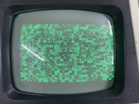
Hi! Can someone assist me
To understand if therr is a bad ram chip? This is a 4032crtc universal board. I only get a garbled screen on power on. Thanks!
 

Attachments

  • IMG_1542.jpeg
    IMG_1542.jpeg
    1.6 MB · Views: 9
  • IMG_1543.jpeg
    IMG_1543.jpeg
    3.6 MB · Views: 9
Back
Top