• Please review our updated Terms and Rules here

Pet video board 320064-02 bad

The question is do you have no Volts here because you have no horizontal drive signal from the PET logic, or because of a fault in the monitor?

What is the cause and what is the effect...

Dave


Maybe it's necessary repair pet board?
 
If the PET mainboard doesn't work - and is not outputting the horizontal drive signal - the monitor will not display a picture.

If this is the case, then yes, you have to repair the PET mainboard first.

If the PET mainboard is outputting the horizontal drive signal, then the problem is in the monitor.

We need to determine which case is true.

Do you have access to a logic probe - or anything that will be able to detect changes in state of a TTL logic signal?

Dave


No i don t have but i can buy a logic probe....
Can i found on Amazon?
 
If the PET mainboard doesn't work - and is not outputting the horizontal drive signal - the monitor will not display a picture.

If this is the case, then yes, you have to repair the PET mainboard first.

If the PET mainboard is outputting the horizontal drive signal, then the problem is in the monitor.

We need to determine which case is true.

As I pointed out in post #25, a digital meter can be used to determine if the H drive pulses are reaching the input transistor of the monitor Q11 and a scope or logic probe not required, did everybody miss reading that post ?

Another quick way with the meter set on DC volts on the collector of the driver transistor Q13. When the pulses (H drive) is there the average voltage there will be about 40/60 x 12 or about 8V and with no H drive the voltage will be about 12V.

Testing both those voltages, at the input on Q11's base and the collector of Q13 (test point 11) would also tell you if there was still a fault where the OP had been working on the circuit, didn't he replace R34 and Q13. In all probability, one of the other transistors in the region of Q13 was also involved in the initial problem, which simply may not have been fixed yet.

(Another way, but it depends on the meter, its frequency response and how it handles a DC offset on an AC voltage, it to set it on the AC volts range and it may tell you if an AC or switching signal is there)

But it may be better for the OP to buy a cheap logic probe as there could be less ambiguity in the test results and they are good to tell you if there is a changing TTL pulse, or if its stuck high or low.

These things are cheap and will do the job:

https://www.ebay.com/itm/Digital-Lo...878483&hash=item1c693dc3f3:g:XeMAAOxymspSHOD9
 
Last edited:
Hi guys,
A very good troubleshooting effort so far!
From what I can tell especially if our OP had disconnected the J7 Video connector from the video board when he took the DC measurements in Message #18, the Video Drive at 5.2V (J7-Pin3) is not running and the Horizontal Drive at 0.17V (J7-Pin5) is also not running.

Combine this with the the Video ON signal at 0.27V (G11-Pin5) in Message #30, this says our control state sequencer outputs on the JK flipflop H8 (on sheet 6) is not running properly. This is not good news as there must be a dozen chips involved including counter countdown chains and state decoders, etc.(sheets 6 and bottom of 7). But this group can get to the bottom of it in short fashion. As previously stated, the OP will need a scope or cheap logic analyzer to do it.
-Dave
 
The output transistor (Q14 in this monitor) is switched ON by stored magnetic energy in the core of the driver transformer T1, at this time, the driver transistor Q13 is switched OFF. When Q13 switches on again (by a signal that originates from the H drive pulses) this is used to switch the output transistor Q14 OFF. This is done because its easy to switch the H output transistor on, the difficult part is to turn it off quickly and effectively for the start of flyback and this requires power from the driver stage to discharge the base-emitter circuit.

I have attached a diagram that elaborates on the oscilloscope recording of the collector voltage of Q13, to explain it and show that the polarity of the windings of T1 are incorrectly marked (by the dots) on the schematic.

Hugo,
This is the clearest explanation of the horizontal drive circuits that I have seen. Thanks so much for the diagram with the circuit analysis. I am not an analog guy so this really helps. I have printed it for my PET files.
-Dave
 
Hugo,
This is the clearest explanation of the horizontal drive circuits that I have seen. Thanks so much for the diagram with the circuit analysis. I am not an analog guy so this really helps. I have printed it for my PET files.
-Dave

Dave,

I discovered this about the driver transformers in horizontal scan stages and also in some designs of switch mode power supplies many years ago. It came about as a result of a faulty switch mode power supply where its output, just from time to time dropped low, it fell out of regulation and shut down. The supply had been through the hands of a number of technicians before I was given it to repair (at a holiday job as a medical student I had to earn extra $) and practically all the parts on the pcb had been replaced, it still had the fault. It was a very very expensive item back then and the company who owned it wanted another go at fixing it.

In this case, the core of the driver transformer, made of two halves glued together, the glue had failed and the halves slightly separated, not easily visible to the eye

This drastically lowered the inductance of the transformer and the stored energy was reduced to the extent, that during the time the output transistor was supposed to be on, the base current dropped and the output transistor would start to come out of saturation and that is why it was failing to regulate and it was a borderline condition too. So I simply pulled it apart, clamped the core halves up with fresh glue and it was fixed. They paid me well and I got some more textbooks.

I'm generally good on analog circuits, and hard wired digital logic, but I struggle a lot on the software and the programming side of things.

Back on the topic of the PET monitor. For the most part I think it is fair to say if a computer was known at one point to be previously working, then it stops, most likely in all probability one fault has caused this.

The fault on the OP's PET monitor, the failure of Q13 and R34 likely was the primary problem and the rest of the computer is ok. What can happen though in attempts to repair assumed faults in other parts of the system by diving in too soon without test information that leads there, ends up creating more faults and the problem spirals out of control. We don't know much about the history of this PET, was it working before the monitor failed. Did any changes to the computer board (like changing IC's) result in failure of the monitor ? The history is always important in diagnosing a problem.

Since the horizontal drive signal is AC coupled into Q11 by the 0.1uF capacitor C16, even if that TTL level got stuck high or low due to a fault on the computer board, this would not result in the failure of Q13, so likely Q13 failed for another reason, perhaps if the signal presented was way higher in frequency than it should be, but that scenario is less likely. Its also possible that the other transistors associated with Q13 have failed, they all need checking in that area.

Of course its all very easy with a scope, but a person has to have one in the first place and be familiar with how to use it. So its pretty tricky for the OP to get the job done without one and just a meter (albeit possible), but that logic probe will help a lot.

Hugo.
 
Last edited:
........I could also add, there are some things that could put Q13 at risk of failure, most other things being ok.

When Q13 is switched on in a sense it protects itself as it adopts a very low C-E voltage. But, when it switches off, most of the damping on the driver transformer comes from the base-emitter current of the output transistor Q14. (Although there are components such as C19,C20,R40 and R43 that help here) if the base-emitter junction of Q14 went open circuit, it is probable that the peak voltage on the collector of Q13 could exceed its maximum ratings and a shorted Q13 could result.

And, obviously if C30 broke down this could result in a very high voltage being applied to Q13's collector and cause failure of it. So its worth checking /testing Q14 and it may well be worth replacing C30, because it might test ok on a low voltage capacitance meter, but break down at higher voltages. A C-B short in the output transistor Q14 would also likely destroy Q13 at the moment it happened. This can happen if the H drive is abnormal and the output transistor turned on for longer than usual, more energy is stored at the end of the scan line and the peak collector voltage, at flyback, on Q14 gets exceeded. So Q14 and Q13 would both fail. That could happen if the H drive signal from the computer board became abnormal due to a fault or interfering with the board/IC's.
 
Last edited:
If the OP doesn't have a logic probe or oscilloscope, then a simple frequency indicator can be made from a 4040 multistage divider, an LED and a series connected current limiting resistor.

Connect your 'probe' to the clock input of the 4040. Disable any set or reset input(s) to the 4040 as required by the data sheet. Connect the LED and series resistor (270 to 470 Ohms) to one of the counter outputs. Select an output appropriate to the expected frequency input so that you can see the LED flash at a sensible rate (say 1 Hz).

A flashing LED indicates that you are measuring a frequency. The flash rate (when upconverted by the divider constant) gives the approximate frequency you are measuring.

Simple, but very effective.

Hugo. Yes, I did see your post. Presumably the OP didn't (which is why I had to remind them of a post of mine that hadn't been answered). My simple way of checking whether the main board is initially at fault is to pull of J7 and check the signals at that point. The OPs measurements indicate everything is not right at this point, so we probably have a fairly significant fault on the divider chain on the main board that we need to investigate first. I then agree with you in that there may be subsequent problems with the monitor.

Dave


Thanks!Today i order logic probe from amazon so i can test ic logic ok?
 
That seems sensible if you do not have one. They are quite cheap and come in very handy for repairing logic circuits.

Have you purchased one with a pulse detection function?

Dave
 
Thanks!Today i order logic probe from amazon so i can test ic logic ok?

Yes,
You can go fairly far in testing with a logic probe. It will tell you if a signal is stuck at a logic low (around zero Volts), or a logic high (around +5 Volts) or if it is pulsing. However there are problems where a signal is pulsing but not with the correct timing in regard to other signals. For these types of problems, an oscilloscope or logic analyzer will be necessary.
 
Hi guys,
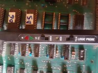
today the logic probe has arrived. What should I start checking? Thanks a lot!
 
The video, horizontal and vertical drive signals on J7 for a start.

Do you see any signs of activity on any of these three signals at all - or are they static high or low logic levels?

You may have to 'experiment' a bit with your logic probe on a known clock signal to see what indication the logic probe gives you.

Dave

Hi Dave,
this is first time for me with logic probe....can i testo on cpu pin 39 maybe?
 
Of course - but remember that this will be 1 MHz (so somewhat higher than the video clocks we will be looking at) - but it will give you some practice with the probe...

Dave
 
Of course - but remember that this will be 1 MHz (so somewhat higher than the video clocks we will be looking at) - but it will give you some practice with the probe...

Dave

Dave it's correct this set in logic probe please?
I can see reset segnal on cpu pin 40 low and after high!
Thanks20190507_185117.jpg
 
Back
Top